Download
1 / 5
50 likes | 75 Vues
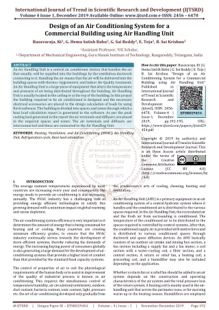
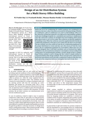
Earlier the use of air conditioning for comfort purpose was considered to be expensive, but now a day, it has been a necessity for all human beings. Window air conditioners, split air conditioners are used in small buildings, offices etc. But, when the cooling load required is very high such as big buildings, multiplex, multi story buildings, hospitals etc. centralized unit central air conditioners used. The central AC's systems are installed away from building called central plant where water or air is to be cooled. This cooled air not directly supplied to the building rooms. When the cooled air cannot be supplied directly from the air conditioning equipment to the space to be cooled, then the ducts are provided. The duct systems carry the cooled air from the air conditioning equipment for the proper distribution to rooms and also carry the return air from the room back to the air conditioning equipment for recirculation. When ducts are not properly designed, then it will lead to problem such as frictional loss, higher installation cost, increased noise and power consumption, uneven cooling in the cooling space. For minimizing this problem, a proper design of duct is needed. Equal friction method is used to design the duct, which is simple method as compared with the other design methods. These work gives the combination of theoretical and software tool to provide a comparative analysis of the duct size. It also gives the comparison between rectangular duct and circular duct. M. Pruthvi Raj | K. Prashanth Reddy | Mussan Shankar Reddy | B. Kranthi Kumar "Design of an Air Distribution System for a Multi Storey Office Building" Published in International Journal of Trend in Scientific Research and Development (ijtsrd), ISSN: 2456-6470, Volume-3 | Issue-3 , April 2019, URL: https://www.ijtsrd.com/papers/ijtsrd23319.pdf Paper URL: https://www.ijtsrd.com/engineering/mechanical-engineering/23319/design-of-an-air-distribution-system-for-a-multi-storey-office-building/m-pruthvi-raj<br>

E N D
International Journal of Trend in Scientific Research and Development (IJTSRD) Volume: 3 | Issue: 3 | Mar-Apr 2019 Available Online: www.ijtsrd.com e-ISSN: 2456 - 6470 Design of an Air Distribution System for a Multi Storey Office Building M. Pruthvi Raj1, K. Prashanth Reddy2, Mussan Shankar Reddy2, B. Kranthi Kumar2 1Associate Professor, 2Student 1,2Department of Mechanical Engineering, Guru Nanak Institute of Technology, Hyderabad, India How to cite this paper: M. Pruthvi Raj | K. Prashanth Reddy | Mussan Shankar Reddy | B. Kranthi Kumar "Design of an Air Distribution System for a Multi Storey Office Building" Published in International Journal of Trend in Scientific Research and Development (ijtsrd), ISSN: 2456- 6470, Volume-3 | Issue-3, April 2019, pp.1208-1212, URL: https://www.ijtsrd.c om/papers/ijtsrd23 319.pdf Copyright © 2019 by author(s) and International Journal of Trend in Scientific Research and Development Journal. This is an Open Access article distributed under the terms of the Creative Commons Attribution License (CC BY 4.0) (http://creativecommons.org/licenses/ by/4.0) I. INTRODUCTION In air-water systems both air and water are used for providing required conditions in the conditioned space. The air and water are cooled or heated in a central plant. The air supplied to the conditioned space from the central plant is called as primary air, while the water supplied from the plant is called as secondary water. The complete system consists of a central plant for cooling or heating of water and air, ducting system with fans for conveying air, water pipelines and pumps for conveying water and a room terminal. The room terminal may be in the form of a fan coil unit, an induction unit or a radiation panel. Even though only one conditioned space is shown in the schematic, in actual systems, the air-water systems can simultaneously serve several conditioned spaces. In case of comfrtness related to light is easy to maintain compared to others like air and water, by using electricity we can maintain intensity of light in houses and buildings etc. Water needs also maintained by borewells, rivers and oceans for small to large application purposes. But it is some what difficult to maintain air quality and humidity in air even though this problem is solved by invention of refrigeration and air conditioning systems. These systems provide cooling and heating effects according to customers choices. ABSTRACT Earlier the use of air conditioning for comfort purpose was considered to be expensive, but now-a-day, it has been a necessity for all human beings. Window air conditioners, split air conditioners are used in small buildings, offices etc. But, when the cooling load required is very high such as big buildings, multiplex, multi-story buildings, hospitals etc. centralized unit (central air conditioners) used. The central AC’s systems are installed away from building called central plant where water or air is to be cooled. This cooled air not directly supplied to the building rooms. When the cooled air cannot be supplied directly from the air conditioning equipment to the space to be cooled, then the ducts are provided. The duct systems carry the cooled air from the air conditioning equipment for the proper distribution to rooms and also carry the return air from the room back to the air conditioning equipment for recirculation. When ducts are not properly designed, then it will lead to problem such as frictional loss, higher installation cost, increased noise and power consumption, uneven cooling in the cooling space. For minimizing this problem, a proper design of duct is needed. Equal friction method is used to design the duct, which is simple method as compared with the other design methods. These work gives the combination of theoretical and software tool to provide a comparative analysis of the duct size. It also gives the comparison between rectangular duct and circular duct. KEYWORDS: Equal friction method, friction loss, duct sizing IJTSRD23319 Different air conditioning (AC) systems are there like split and window AC systems these are generally used for small load applications like offices and small rooms and houses etc. For large scale industries and high load application these systems are not suitable for this purpose heating, ventilation and air conditioning systems are invented (HVAC). Human body comfortable at 22?-25?, if temperature in atmosphere is below and above to this temperature human feels uncomfortable, in order to solve this problem HVAC systems are employed. HVAC system installed to achieves environmental requirements of comforts of occupants present in that place where system is installed, and the main aim of this system is to provide thermal comfortness to occupants. This can be done by changing outdoor air conditions to desired air condition of the occupants, depending upon outdoor quality of air indoor air quality is modified or conditioned on basic of choice of occupants in that place where HVAC system is installed to maintain air conditioning process of that area. In general like in split and window Ac systems cooled air is directly distributed to surroundings from air conditioning systems, there is no intermediate equipment or device in order to transfer cooled air from system to surrounding @ IJTSRD | Unique Paper ID – IJTSRD23319 | Volume – 3 | Issue – 3 | Mar-Apr 2019 Page: 1208
International Journal of Trend in Scientific Research and Development (IJTSRD) @ www.ijtsrd.com eISSN: 2456-6470 because capacity of this type of systems is limited to small amount of load only. But in case of large load applications like commercial buildings and institutional buildings etc they need intermediate device to transfer cooled air from air conditioning system to surroundings (different portions of buildings). This device is called duct which is used to supply cold air and extract hot air from surroundings, and it is used to recirculation purpose. Installation or selectin of HVAC system depends on following parameters or factors like climate conditions, building design, building age, project budget and owner preferences as shown in Fig.1. stages involved in this project, first of space need to consider like two floor shopping complex floor wise area and number of sections in it. Duct arrangement design on basis of number of workspaces in complex, finally cooling and heating load condition on basis of factors as shown in Fig.3. like occupancy, occupants load, Building thermal load, Light and power supply load and air for ventilation purpose. In order to calculate cooling and heating loads for any building first occupants load and thermal loads involves inside building is calculated. Fig.2. Stages of HVAC System Design in Complex Fig.1. System Selection Factors In this project for designing and analysing AC setting for two floor shopping complex Autodesk Revit MEP software is used, it is building information modelling software. The main features of this software are accurate design, documentation within in a short span of time and one of the best features is that if one part is modified with respect to its other parts also modified it increases productivity of design. HVAC systems are broadly classified as four categories, they are all air systems, all water system, air-water systems and unitary systems. Unitary systems used where low cost is taken as budget of project, for control of humidity all air systems used, large exposure purpose air-water systems are employed, and all water systems are employed for limited space and existing buildings [1].Various uncertainties are to be considered in case of methodology of primary HVAC systems these must be optimized in order to get good results [2]. Chiller and heater in HVAC systems (Theatre) are consuming more energy due to this energy scarcity occurs to the system in order to overcome this problem heating devices are replaced with condenser of heat pipe heat exchangers [3]. Subspace identification technique is used to model thermodynamics of each zone independently in order to do thermal predictions [4]. consumption takes place in HVAC systems by replacing Non- renewable energy sources with renewable energy sources [5]. II. Methodology Methodology for this project involves different stages as shown in Fig.2. like space available for system arrangement and installation, duct design for the shopping complex and cooling and heating load calculations. These are the major Fig.3. Parameters for Load Calculations III. This project involves air conditioning system design and analysis for two floor shopping complexes, for this purpose individually load calculations are to be done for first as well as second floors. In general floor to floor work spaces are different compared to other floors so individual calculations are required. In order to design duct arrangements for two floors Revit software is used, it gives information and documentation about building in design process, design procedure for two floors as discussed below ?First draw a rectangle (with building area) and then divide the sections in it these are the room in that floor and create windows. In this step floor layouts are created as shown in Fig.4. and Fig.5. Air-conditioning System Design for Two Floors Minimization of energy @ IJTSRD | Unique Paper ID - IJTSRD23319 | Volume – 3 | Issue – 3 | Mar-Apr 2019 Page: 1209
International Journal of Trend in Scientific Research and Development (IJTSRD) @ www.ijtsrd.com eISSN: 2456-6470 Fig.4. First Floor Layout Fig.7. Second Floor Ceiling with Duct Layout ?Create spacing and zoning for different workspaces in two floors as shown in Fig.8. and Fig.9. Fig.5. Second Floor Layout ?After layout, ceiling drawings and duct arrangements for rooms depends on their load capacity are drawn as shown in Fig.6. and Fig.7. Fig.8. First Floor Spacing and Zoning ?After creation of duct arrangement by using analyse option get the load reports for floors. Volumes of different workspaces in two floor shopping complexeS Fig.6. First Floor Ceiling with Duct Layout @ IJTSRD | Unique Paper ID - IJTSRD23319 | Volume – 3 | Issue – 3 | Mar-Apr 2019 Page: 1210
International Journal of Trend in Scientific Research and Development (IJTSRD) @ www.ijtsrd.com eISSN: 2456-6470 Table I: First Floor Load Values Peak Cooling Load (Btu/h) 73,054.9 70,734.3 157,947.4 70,239.4 92,595.0 74,990.5 67,954.6 Ara (SF) 860 860 1,940 860 1,154 860 857 Volume (CF) 7,744.00 7,744.00 17,464.00 7,744.00 10,384.00 7,744.00 7,714.00 Cooling Airflow (CFM) 3,645 3,530 7,882 3,505 4,620 3,742 3,391 Peak Heating Load (Btu/h) 8,814.6 7,906.7 18,003.6 8,528.9 10,872.9 8,814.6 7,802.3 Heating Airflow (CFM) 422 378 861 408 520 422 373 Space Name 1 WORK SPACE 2 WORK SPACE 3 WORK SPACE 4 MANAGER 5 RECEPTION 6 ACCOUNTS 7 CORRIDOR Table 2 second floor load values Peak Cooling Load (Btu/h) 14,089.00 126,652.8 10,384.00 93,714.6 9,064.00 83,386.1 13,069.00 116,393.9 16,789.00 163,209.5 Area (SF) 1,565 1,154 1,007 1,452 1,865 Volume (CF) Cooling Airflow(CFM) 6,287 4,652 4,139 5,778 8,101 Peak Heating Load (Btu/h) 15,502.5 10,811.1 9,787.5 13,499.4 17,015.6 Heating Airflow (CFM) 742 517 468 646 814 Space Name 8 CORRIDOR 9 WORK SPACE 1 0 WORK SPACE 1 1 WORK SPACE 1 2 CONFERENCE Table 3 Building Summary Inputs Building Type Area (SF) Volume (CF) Calculated Results Peak Cooling Total Load (Btu/h) Peak Cooling Month and Hour Peak Cooling Sensible Load (Btu/h) 1,192,045.0 Peak Cooling Latent Load (Btu/h) Maximum Cooling Capacity (Btu/h) 1,225,873.6 Peak Cooling Airflow (CFM) Peak Heating Load (Btu/h) Peak Heating Airflow (CFM) Checksums Cooling Load Density (Btu/(h·ft²)) Cooling Flow Density (CFM/SF) Cooling Flow / Load (CFM/ton) Cooling Area / Load (SF/ton) Heating Load Density (Btu/(h·ft²)) Heating Flow Density (CFM/SF) Office 14,437 129,933.00 1,225,873.6 May 14:00 33,828.6 59,272 137,359.8 6,572 84.91 4.11 580.21 141.32 9.51 0.46 IV. Cooling and heating loads are calculated on basis of different parameters involved in calculations, for two different floors individually loads are calculated results are listed in Table I. and Table II, building summary mentioned in Table III, these are all generated in Revit software. These tabulated results are automatically generated by Revit software by entering input values related to building and individual floor number of workspaces and areas, HVAC system setting for two floor shopping complex gives different conclusion in case of loads of two individual floors, cooling and heating air flows as discussed below Peak cooling and heating loads for two floor shopping complexes are different for individual floors, second floor require more load even though it is having less workspaces. ?Cooling air flow requirement for first floor is less compared to second floor because of low peak heating loads of first floor. ?Heating air flow is more in first floor compared to second floor because of peak cooling load is less in first floor. ?Load requirements are not depending on number of workspaces it depends on capacity of workspace and occupancy capacity of it. ACKNOWLEDGMENT I owe my immense thanks to my project Guide M. PRUTHVI RAJ, Assistant professor DEPARTMENT OF MECHANICAL ENGINEERING Guru Nanak Institute of Technology for this sustained interest, constructive criticism and constant encouragement at every stage of this Endeavour. Also, I heart fully thank Dr. B. Vijaya Kumar, professor and head of department, Guru Nanak Institute of Technology for his constant encouragement. I extended my deep sense of gratitude to the principle Dr. S. Sreenatha Reddy and the management of Guru Nanak Institute of Technology for providing of the best amenities to enable us to complete my project in stipulated time. Results and Discussion @ IJTSRD | Unique Paper ID - IJTSRD23319 | Volume – 3 | Issue – 3 | Mar-Apr 2019 Page: 1211
International Journal of Trend in Scientific Research and Development (IJTSRD) @ www.ijtsrd.com eISSN: 2456-6470 REFERENCES [1]S. M. Gheji, K. S. Kamble and A. A. Gavde “Basic Classification of HVAC system for Selection Guide” International Journal of Innovative Research in Science, Engineering and Technology Vol. 5, No. 4, 2016, pp. 6077-6086. Theatres International Journal of Renewable Energy Research Vol. 4, No. 3, 2014, pp. 587-593. by Using Heat Recovery Devices” [4]O. Tsakiridis, D. Sklavounos and E. Zervas “A Comfort- aware Energy HVAC System Based on Subspace Identification Method” Journal of Energy Vol. 2016, pp. 1-13. [2]Harkamaljeet Singh Bhullar and Vikram Kumar Kamboj “Energy conservation of heat, ventilation & Air Conditioning System with the Help of Fuzzy Controllers” International Journal of Scientific & Engineering Research Vol. 2, No. 10, 2011, pp. 1-8. [5]Arsha Viswambharan, Sheetal Kumar Patidar and Khyati Saxena “Sustainable HVAC Systems in Commercial and Residential Buildings International Journal of Scientific and Research Publication Vol. 4, No. 4, 2014, pp. 1-4. [3]Mohammad Ahmadzadehtalatapeh “Improving the Energy Performance of HVAC System Operating @ IJTSRD | Unique Paper ID - IJTSRD23319 | Volume – 3 | Issue – 3 | Mar-Apr 2019 Page: 1212