Download
1 / 44
440 likes | 804 Vues
Sketch Recognition for Digital Circuit Diagrams in the Classroom. Christine Alvarado Harvey Mudd College March 26, 2007. Joint work with the HMC Sketchers group: Aaron Wolin , Ned Burns , Jason Fennell, Max Pfleuger, Devin Smith, Paul Wais, Howard Chen, Matt Weiner, Prof. Sarah Harris.

E N D
Sketch Recognition for Digital Circuit Diagrams in the Classroom Christine Alvarado Harvey Mudd College March 26, 2007 Joint work with the HMC Sketchers group: Aaron Wolin, Ned Burns, Jason Fennell, Max Pfleuger, DevinSmith, Paul Wais, Howard Chen, Matt Weiner, Prof. Sarah Harris
Sketching In Education Digital Circuit Design
Educational Technologies "Most of the time the lab was more about battling Xilinx than actually learning anything useful" –HMC, E85 student
Correct! AND-2 OR-2 AND-2 XOR-2 XOR-2
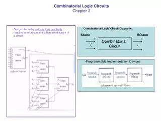
Goals Build a sketch-based circuit simulation tool that: • is robust enough for real use • allows students to sketch as freely as possible • is easier to use than current software We need: • An integrated circuit simulation system • Improved free-sketch recognition algorithms • An understanding of user interface issues
Integrated System Overview Front End hand-drawn sketch Circuit Recognitionand Translation Verilog file Simulation (Xilinx)
Integrated System Overview Front End User Interface Design hand-drawn sketch Recognize Symbols Free-sketch Recognition Construct Circuit Diagram Parsing Translate to Verilog Verilog file Simulation (Xilinx)
Sketch Recognition Subtasks Stroke Fragmentation NOR Symbol Recognition Stroke Grouping
A Typical Approach to Recognition Stroke Fragmentation Stroke Grouping Symbol Recognition
A Typical Approach to Recognition: Problem incorrect grouping
Why is Grouping Hard? • No clear boundaries in space…
Why is Grouping Hard? • No clear boundaries in space or time
A Typical Approach to Recognition: Problem ??? Stroke Grouping cannot be done without recognition (But recognition cannot be done without stroke grouping)
Our Approach Stroke Fragmentation Single-StrokeRecognition Stroke Grouping Symbol Recognition
Our Approach Stroke Fragmentation Single-StrokeRecognition Stroke Grouping Symbol Recognition
Single-Stroke Recognition • Goal: Label each stroke as WIRE, GATE or SIGNAL • Method: Conditional Random Field Approach based on Yuan Qi, Martin Szummer, Thomas P. Minka. Diagram Structure Recognition by Bayesian Conditional Random Fields June 2005 Proc Comp. Vision Pattern Recogn. (CVPR) C. Schmid and S. Soatto and C. Tomasi 191--196 gate gate wire gate signal wire gate wire
Conditional Random Field (CRF) • Determines P(y|x) • y: vector of labels (wire or gate), one for each fragment (stroke) • x: set of all observations (stroke features)
Data Collection • Goal: Free sketching in engineering education • Method: • Distributed Tablet Computers to ~35 students in HMC E85 (digital circuit design) and E84 (analog circuit design) • Collected sketches from notes, homeworks, and labs But what about labeling?
Labeling Tasks • Stroke Fragmentation • Stroke Grouping and Labeling
Designing the UI • User Study to examine: • Recognition Triggers (button, gesture, pause) • Feedback mechanisms (color, symbol, text) • Error Rates and Types • Preliminary Results • Users prefer active recognition trigger • Trigger must be reliable • Users rarely trigger recognition
(Some Immediate) Future Work Stroke Fragmentation Single-StrokeRecognition Stroke Grouping Symbol Recognition Multi-class recognition wire vs. gate vs. signal
Conclusion • Single-stroke recognition Improved grouping + recognition • Direct manipulation labeling more complete datasets • Robust free-sketch recognition lower barriers to learning
CRF Probability Distribution The probability of a set of labels given data Want to maximize P(y|x) Normalizing term Local compatibility with labels Compatibility based on context Normalize by sum over all possible label sets. Nasty term Need approximation to make this computationally feasible
Feature functions • CRF cannot use raw stroke data • Feature functions extract useful numerical data • Vector of data extracted for each node and pair of adjacent nodes P(y|x) What are these observations?
Parameters • Relative usefulness of features for classification needs to be accounted for • Parameters act as weights for individual features • Weighted features combined with a sum • Represented with a dot product
Site Potentials • Measure compatibility between labels and a node • The exponential makes the math nicer • All potentials combined with a product feature function weight vector Site Potential
Interaction Potentials • Where the CRF gets its power • Uses context by measuring compatibility between pairs of adjacent nodes and pairs of labels • Mathematically, same story as site potentials feature function weight vector Interaction Potential
What does a CRF need? • Gather data on the sketch and individual strokes (feature functions) • Determine weights (training) • Maximize P(y|x) in a computationally feasible way (inference) • Not going to talk about this
Feature Functions • Can’t pass stroke data directly into the CRF • Feature functions translate raw stroke data into simple linear values that the CRF can act on • We required returned values to be in the range of [-1, 1] • In theory other ranges work, but we had problems with them
Mathematical Limitations • The CRF must respond linearly to the values returned by feature functions • This can be problematic if the returned value has physical meaning, like the length of a stroke • To deal with features like length we created a couple of different features for whether the length was within a certain range
Site Feature: Turning • Calculates the total quantity of rotation in a stroke • After calculating the value of Turning, we returned four different values for different regions • To see why we need to do this, consider the red, blue, and green strokes below
Interaction Feature: T-Junction • Detects whether two strokes are configured in a T-Junction with each other • Might occur where a wire meets a gate • Note that this function is non-symmetric • We have to differentiate the cross from the stem of a T-Junction • We use two identical versions of this function with the arguments reversed
Parameters • We still need a list of weights or parameters relating every site feature to every label, and every interaction feature to every pair of labels • Must learn parameters from labeled data
Likelihood function • The likelihood function is a representation of how well a given set of parameters classifies a given data set • We actually use (-log(likelihood)) to make the math simpler • Training allows us to find
Training: Idea • How can we minimize ? • Take the derivative and set it to 0? • Equation is too complicated • Gradient descent: Locally follow the gradient down to the lowest point (hopefully!) [evaluated on training data] [w,v] optimal parameters
Future Work • More / better feature functions • Computational issues • Numerical under- and overflow • Multi-Pass CRFs • Find Gates and Wires • Train the CRF again on the gates, distinguishing the type of gate • Circuit understanding, interface with Xilinx