Analog Sensors
760 likes | 1.92k Vues
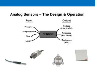
Analog Sensors. 6.3 Analog Sensors. A number of sensors have analog output signal rather than digital signals A/D converter is required to connect to CPU Examples: • Microphone • analog infrared distance sensor • analog compass • barometer sensor. Ohm's Law.

Analog Sensors
E N D
Presentation Transcript
6.3 Analog Sensors • A number of sensors have analog output signal rather than digital signals • A/D converter is required to connect to CPU • Examples: • Microphone • analog infrared distance sensor • analog compass • barometer sensor
Ohm's Law • Ohm's law; explains the relationship between voltage (V), current (I), and resistance (R): V = I R • Simply put: the voltage between two points in an electronic circuit is equal to the product of the amount of current flowing through them and the amount of resistance between them. • Voltage is measured in Volts (V), current in Amperes (A), and resistance in Ohms (Omega).
Combining resistances • It's not hard to figure out how much resistance one resistor gives (since they are labeled!). • But what happens if you put one resistor R1 after another R2, i.e., connected them in series? • The current I flowing through any number of resistors has to be equal, since it has only one route to flow on, as it goes from one resistor to the next. • What happens to the voltage V? • Recall Ohm's law: V = I R • = I (R1 + R2) • = I R1 + I R2 • Suppose we measure the voltage across R1, i.e., the voltage between the input point V and the connection between R1 and R2, would would it be? • It would be I R1 Volts. Similarly, if we measure the voltage across R2, i.e., the voltage between the connection between R1 and R2 and ground, what will it be? It will be I R2. • The total voltage in an electronic circuit has to add up; therefore, the input voltage V has to equal the output voltage, after the drop across the two resistors, R1 and R2. • Therefore, since voltages in a series add, so do resistances in a series. Practical use of your undergraduate electronics
Dividing voltage • Suppose we take the voltage out at the point between R1 and R2, what will the amount of that voltage Vout be? • Use Ohm's law again: V = I R => I = V / R = V / (R1 + R2) • Then the voltage drop across R2, is the product of the above current I and R2: • Vout = V R2 / (R1 + R2) • What if R1 = R2? = V R2 / 2 R2 = V / 2 • This is a voltage divider. To summarize: voltage can be divided by using two equal-value resistors in series. • You will learn in the lab how to bridge the gap between this type of laws of electronics to physical sensors all the way to robot behavior.
Analog Sensors • The voltage at the signal pin can be simply calculated by: • V sig = 5 • check if one sensor fell out: write a piece of code that checks the values of the analog ports that you have sensors plugged into. • If that value is above 250 or so, have it tell you to check the sensor. • The analog ports all have a pull up resistor which is a 47K resistor between +5 volts and the signal input. • The analog readings are generated by measuring the amount of current flow through the pull up resistor. • If no current flows through the resistor, the voltage at the signal input will be +5 volts and the analog value will be 255.
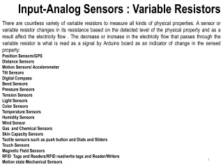
Resistive Sensors • The resistance of resistive analog sensors, like the bend sensors or potentiometers, change with changes in the environment: • an increase in light, • or a physical deformation. • The change in resistance causes a change in the voltage at the signal input by the voltage divider relation. *
Transitive Analog Sensor • Transitive analog sensors, like the photo transistors and reflectance sensors, work like a water faucet. • Providing more of what the sensor is looking for opens the setting of the valve, allowing more current to flow. • This makes the voltage at the signal decrease. • A photo transistor reads around 10 in bright light and 240 in the dark. • One problem that may occur with transitive sensors is that the voltage drop across the resistor may not be large enough when the transistor is open. • Some transitive devices only allow a small amount of current to flow through the transistor.
Transitive Analog Sensor (cont) • A larger range for the sensor can be accomplished by putting a larger pull-up resistor. • By having a larger resistor, the voltage drop across the pull-up resistor will be proportional to the resistance. • Martin’s book gives examples of use and mountings for each type of sensor. • Keep in mind that these are only simple examples and are not the only possible uses for them. • It's up to you to make creative use of the sensors you have.
Sensor Interfacing to Analog Inputs photocell element • Vsensvoltage at the center tap of the two resistors is proportional to the ratio of the two resistances. • Rphoto = 47KW, Vsens = 2.5 v (exactly) • Rphoto << 47KW, Vsens ~= gnd • Rphoto >> 47KW, Vsens ~= +5 v Two resistors form voltage divider circuit Also possible to connect circuits that generate a voltage
Sensor Interfacing to Analog Inputs 0 to 5 volts are converted into 8–bit numbers 0 to 255 (decimal) (A/D conversion) • When the photocell resistance is small • (brightly illuminated), the Vsens ~= 0v • When the photocell resistance is large • (dark), Vsens ~= +5 v
Resistive Position Sensors Potentiometers. Glowes. Pads. Bend Sensors. Other….?
Pressure Pad You can purchase such pad for Nintendo games
Pressure Pad • LM339 is a quad comparator circuit: • Output will be +6V • Another approach is to use ohm meter to detect the resistance change which would be proportional to amount of pressure applied.
Potentiometer: the main ideas • Potentiometers are very common for manual tuning; you know them from some controls (such as volume and tone on stereos). • Typically called pots, they allow the user to manually adjust the resistance. • The general idea is that the device consists of a movable tap along two fixed ends. • As the tap is moved, the resistance changes. • As you can imagine, the resistance between the two ends is fixed, but the resistance between the movable part and either end varies as the part is moved. • In robotics, pots are commonly used to sense and tune position for sliding and rotating mechanisms.
Potentiometers versus resistance sensors • Fixed Rotation Sensors • Easy to find, easy to mount • Light Sensor • Good for detecting direction/presence of light • Non-linear resistance • Slow response Potentiometer Look to catalogs: Cadmium Sulfide Cell HANDYBOARD: Gleason Research. http://www.gleasonresearch.com/ http://handyboard.com DISTRIBUTOR OF AGE BEND SENSOR: Images Company: http://www.imagesco.com PITSCO LEGO DACTA, JAMECO, ETC - see the book and my webpage.
Potentiometers • Manually-controlled variable resistor, commonly used as volume/tone controls of stereos • Mechanical varieties: • Linear and rotational styles - make position sensors for both sliding mechanisms and rotating shafts • Resistance between the end taps is fixed, but the resistance between either end tap and the center swipe varies based on the position of the swipe • Electrical varieties: • Linear taper - linear relationship between position and resistance. Turn the pot 1/4 way, the resistance between the nearer end and the center is 1/4 of end-to-end resistance • Audio taper - logarithmic relationship between position and resistance. At one end, 1/4 turn would swipe over a small bit of total resistance range, while at the other end, 1/4 turn would be most of the range
Figure 5.5: Potentiometer Assemblies • Kits contain several sizes of potentiometers, also known as variable resistors. • Potentiometers should be wired with Vcc and ground on the two outside pins, and the signal wire on the center tap. • This will, in effect, place the resistance of the potentiometer in parallel with the 47K pull-up on the expansion board and is more stable than just using one side and the center tab to make a plain variable resistor
Two ways of using Potentiometers as Resistive Position Sensors works best when the potentiometer resistance is small enough such that a 47K resistance in parallel with the pot’s resistance has only a small effect 3-terminal potentiometer 2–terminal potentiometer works best when the pot’s value is large 2-terminal potentiometer
Various uses of Potentiometers • Potentiometers have a variety of uses: • In the past, they have been used for menuing programs • For angle measurement for various rotating limbs • For scanning beacons. • They can be used with a motor to mimic servos, but that's a difficult task. • It is important to notice that the pots are not designed to turn more than about 270 degrees. • Forcing them farther is likely to break them. Tell about our previous project of animation inverse kinematics robot with many pots and A/D board. (the one that was stolen)
Various uses of Potentiometers • A potentiometer can be attached to a LEGO beam • such that it can be used in place of a bend sensor. • The rotation of the beam will produce a rotation in the potentiometer. • See if you can come up with an assembly that can be used in place of a bend sensor. • The advantage to such a sensor is that it is much sturdier than the bend sensor. • The disadvantage is that it is bulkier.
Linear Potentiometers and their use in HandyBoard • A linear potentiometer can be used to measure precise linear motion, • such as a gate closing, • or a cocking mechanismfor ring balls or blocks. • Frob-knob • The frob knob is the small white dial on the lower left corner of the Expansion Board. • It returns values between 0 and 255 and provides a handy user input for adjusting parameters on the y or for menuing routines to select different programs. • You may find it useful to glue a small LEGO piece to the frob knob to make turning it easier.
Homework Assignment • Try to find in your storage any kind of sensors that you do not use and bring them to the robotics labs. • The ECE 271 and the high school students will possibly use it for projects if you will not. • Look around the lab and try to identify sensors and devices that we talked about.
Resistive Position Sensors: bending • We said earlier that a photocell is a resistive device, i.e., it senses resistance in response to the light. • We can also sense resistance in response to other physical properties, such as bending. • The resistance of the device increases with the amount it is bent. • These bend sensors were originally developed for video game control • They are generally quite useful: • Nintendo Powerglove • Video game accessories are in general useful for robotics and virtual reality and very cheap.
Resistive Bend Sensors • Resistance = 10k to 35k • Force to produce 90deg = 5 grams • www.jameco.com = 10$
Bend Sensors You can remove it from Nintendo gloves • Useful for contact sensing and wall-tracking • The bend sensor is a simple resistance • As the plastic strip is bent (with the silver rectangles facing outward), the resistance increases
Resistive Position Sensors • Mechanically, the bend sensor is not terribly robust, and requires strong protection at its base, near the electrical contacts. • Unless the sensor is well-protected from direct forces, it will fail over time. • Notice that even in a good arrangement, repeated bending will wear out the sensor. • Remember: a bend sensor is much less robust than light sensors, • although they use the same underlying resistive principle.
Applications of Resistive Analog Sensors Sensor • Measure bend of a joint • Wall Following/Collision Detection • Weight Sensor Sensors Sensor
Inputs for Resistive Sensors V1 Voltage divider: You have two resisters, one is fixed and the other varies, as well as a constant voltage V1 – V2 * (R2/R1+R2) = V R1 V Analog to Digital (pull down) R2 V2 micro Known unknown measure micro + Binary Threshold Single Pin Resistance Measurement - Comparator: if voltage at + is greater than at -, high value out
Sensor Assembly • You should have read the section on the chapter of Martin’s book on the types of connectors used with the 6.270 board. • This is an important concept to understand before building your sensors. • When building your sensors, do not make your wires too long. • Excess wiring has a tendency to get caught in gears and other mechanisms.
Sensor Assembly Homework • Start out with sensor wires no longer than 1 foot long and when your finally decide on your robot configuration, you can modify to length. • Just build a few of each type so you can play with them. • Start out with building simple sensors like one or two switches. • The more complicated ones will be the analog sensors that use IR. • Go to lab and familiarize yourself with Lego kit sensors and how to use them. • I purchased many good sensors from Wacky Willy, Tek Country Store and Radio Shack. In Goodwill you can buy old toys like Nintendo gloves or jumping pads that can be used. They are in the lab and you can use them. You have to notify me or lab assistant.
6.4 A/D Converter • Signal has to be provided at correct level, e.g. between 0 .. 5V • If multiple channels are read: low internal resistance of signal line is important • A/D converter translates analog voltage level into digital value • Digital output from A/D converter can be – parallel (e.g. 8 bit, direct connection to data bus) – serially digital (provide programmed clock signal to converter to read data bit by bit)
Questions for students • Use of Ohm’s Law and Voltage division in designing and adaptation of sensors. • Applications of pressure pads and potentiometers in robots. Discuss stationary and mobile robots. • Bend sensors and their uses. • A/D converters in robotics applications. • List applications of D/A converters.
Sources • T Braunl • A. Ferworn • Saúl J. Vega • Daisy A. Ortiz • Raúl E. Torres • Maja Mataric • Ali Emre Turgut • Dr. Linda Bushnell • Web Site: http://www.ee.washington.edu/class/462/aut00/ • Robotic Explorations: A Hands-on Introduction to Engineering, Fred Martin, Prentice Hall, 2001.