INTRODUCTION TO DIGITAL SIGNAL PROCESSORS
290 likes | 713 Vues
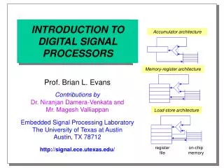
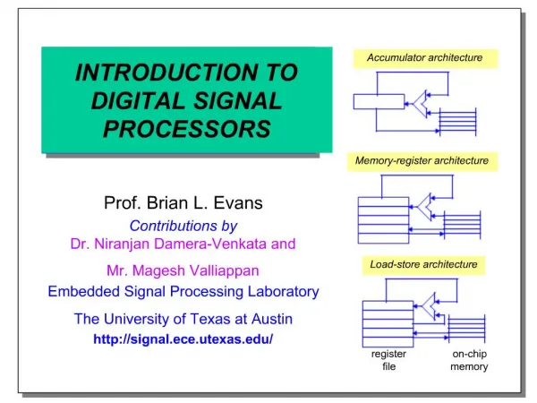
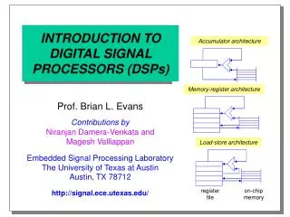
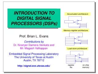
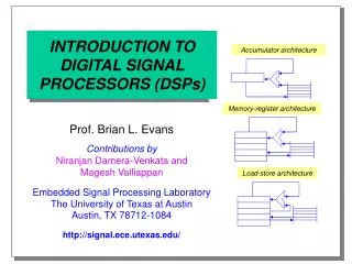
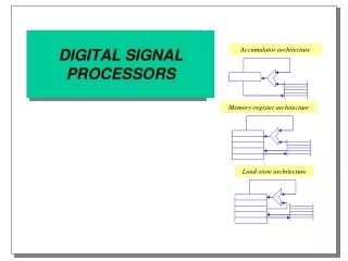
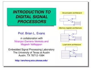
INTRODUCTION TO DIGITAL SIGNAL PROCESSORS. Accumulator architecture. Memory-register architecture. Prof. Brian L. Evans in collaboration with Niranjan Damera-Venkata and Magesh Valliappan Embedded Signal Processing Laboratory The University of Texas at Austin Austin, TX 78712-1084

INTRODUCTION TO DIGITAL SIGNAL PROCESSORS
E N D
Presentation Transcript
INTRODUCTION TODIGITAL SIGNALPROCESSORS Accumulator architecture Memory-register architecture Prof. Brian L. Evans in collaboration withNiranjan Damera-Venkata andMagesh Valliappan Embedded Signal Processing LaboratoryThe University of Texas at AustinAustin, TX 78712-1084 http://anchovy.ece.utexas.edu/ Load-store architecture
Outline • Signal processing applications • Conventional DSP architecture • Pipelining in DSP processors • RISC vs. DSP processor architectures • TI TMS320C6x VLIW DSP architecture • Signal and image processing applications • Signal processing on general-purpose processors • Conclusion
Signal Processing Applications • Low-cost embedded systems • Modems, cellular telephones, disk drives, printers • High-throughput applications • Halftoning, radar, high-resolution sonar, tomography • PC based multimedia • Compression/decompression of audio, graphics, video • Embedded processor requirements • Inexpensive with small area and volume • Deterministic interrupt service routine latency • Low power: ~50 mW (TMS320C5402/20: 0.32 mA/MIP)
Conventional DSP Architecture • High data throughput • Harvard architecture • Separate data memory/bus and program memory/bus • Three reads and one or two writes per instruction cycle • Short deterministic interrupt service routine latency • Multiply-accumulate (MAC) in a single instruction cycle • Special addressing modes supported in hardware • Modulo addressing for circular buffers (e.g. FIR filters) • Bit-reversed addressing (e.g. fast Fourier transforms) • Instructions to keep the 3-4 stages of the pipeline full • Zero-overhead looping (one pipeline flush to set up) • Delayed branches
Conventional DSP Architecture (con’t) Data-shifting • Modulo addressing • implementing circular buffers and delay lines Time Buffer contents Next sample xN-K+1 xN-1 xN+1 xN-K+1 xN n=N xN-K+2 xN xN-K+3 xN+1 n=N+1 xN+2 xN-K+3 xN+1 xN-K+4 xN+2 n=N+2 xN+3 Modulo addressing Time Next sample Buffer contents • Bit reversed addressing • used to implement the radix-2 FFT n=N xN-2 xN-K+1 xN xN+1 xN-1 xN-K+2 xN+2 xN-2 xN+1 xN xN xN-K+3 xN-1 xN-K+2 n=N+1 xN-2 xN+1 xN xN-1 xN xN+2 xN-K+3 xN-K+4 xN-K+4 n=N+2 xN+3
Conventional DSP Architecture (con’t) • Market share: 95% fixed-point, 5% floating-point • Each processor has dozens of configurations • Size and map of data and program memory • A/D, input/output buffers, interfaces, timers, and D/A • Drawbacks to conventional DSP processors • No byte addressing (desirable for image and video) • Limited on-chip memory • Limited addressable memory on fixed-point DSPs: except Motorola 56300 (16 Mw data; 32 Mw program) and C548/C549/C54xx (8 Mw data; 256 kw program) • Non-standard C extensions to support fixed-point data
Pipelining Sequential(Motorola 56000) Fetch Decode Read Execute Pipelined(Most conventional DSP processors) Fetch Decode Read Execute Superscalar(Pentium, MIPS) • Managing Pipelines • compiler or programmer • interlocking • hardware instruction scheduling Fetch Decode Read Execute Superpipelined (CDC7600) Fetch Decode Read Execute
Pipelining: Operation Fetch Decode Read • Time-stationary pipeline model • Programmer controls each cycle • Motorola DSP56001 • Data-stationary pipeline model • Programmer specifies data operations • TMS320C30/40 • Interlocked pipeline • Programmer is “protected” from pipeline effects Execute F D R E C D E F G H I J K - L D E F G H I J K L L B C D E F G H I J K - L A B C D E F G H I J K - L MAC X0,Y0,A X:(R0)+,X0 Y:(R4)-,Y0 MPYF *++AR0(1),*++AR1(IR0),R0
Pipelining: Hazards Fetch Decode Read • A control hazard occurs when a branch instruction is decoded • “Flush” the pipeline • or: Delayed branch (expose pipeline) • A data hazard occurs because an operand cannot be read yet • Intended by programmer • or: Interlock hardware inserts “bubble” Execute F D R E D E F br G - - X Y Y Z CD E F br - - - X - Y Z BCD E F br - - - X - Y Z ABCD E F br - - - X - Y Z TMS320C5x example LAC #064h SAMM AR2 NOP LACC *- LAR AR2, DATA LACC *-
Pipelining: Avoiding Control Hazards Fetch Decode Read • A repeat instruction repeats one instruction or a block of instructions after repeat • The pipeline is filled with repeated instruction (or block of instructions) • Cost: one pipeline flush only Execute A key factor in the numeric performance of DSPs is the provision of special hardware to perform looping. F D R E D E F rpt X X X X X X X X C D E F rpt - - X X X X X B CD E F rpt - - X X X X ABCD E F rpt - - X X X RPT COUNT TBLR *+
RISC vs. DSP: Instruction Encoding • RISC: Superscalar Reorder Load/store FP Unit Integer Unit • DSP: Horizontal microcode Load/store Load/store Address ALU Multiplier
RISC vs. DSP: Memory Hierarchy • RISC Registers I/DCache Physical memory Outof order TLB TLB: Translation Lookaside Buffer Internal memories I Cache • DSP Registers External memories DMA Controller DMA: Direct Memory Access
TI TMS320C6x VLIW DSP Architecture Simplified Architecture Program RAM Data RAM or Cache Addr Internal Buses DMA Serial Port Host Port Boot Load Timers Pwr Down Data .D1 .D2 .M1 .M2 External Memory -Sync -Async Regs (A0-A15) Regs (B0-B15) .L1 .L2 .S1 .S2 Control Regs CPU
TI TMS320C6x VLIW DSP Architecture • One instruction cycle per clock cycle • Two parallel data paths with single-cycle units: • Data unit - 32-bit address calculations (modulo, linear) • Multiplier unit - 16 bit x 16 bit with 32-bit result • Logical unit - 40-bit (saturation) arithmetic & compares • Shifter unit - 32-bit integer ALU and 40-bit shifter • 16 32-bit general purpose registers in each path • 40 bits can be stored in adjacent even/odd registers • 32-bit addressing of 8/16/32 bit data • Fixed-point (C62x) and floating-point (C67x) • C67x computes floating-point multiply in 4 cycles
TI TMS320C6x VLIW DSP Architecture • TMS320C6211: $21 in volume • 150 MHz, 300 million MACs/sec, 1200 RISC MIPS • on-chip: 4k x 8 bits program and 4k x 8 bits data(plus 64k x 8 bits L2 cache) • Deep pipeline • 7-11 stages in C62x: fetch 4, decode 2, execute 1-5 • 7-16 stages in C67x: fetch 4, decode 2, execute 1-10 • If a branch is in the pipeline, interrupts are disabled (the latency of a branch instruction is 5 cycles) • Avoid branches by using conditional execution • No hardware protection against pipeline hazards • Compiler and assembler must prevent pipeline hazards
C5x and C6x Addressing Modes • Immediate • The operand is part of the instruction • Register • The operand is specified in a register • Direct • The address of the operand is part of the instruction (added to imply memory page) • Indirect • The address of the operand is stored in a register TMS320C5x TMS320C6x ADD #0FFh add .L1 -13,A1,A6 (implied) add .L1 A7,A6,A7 ADD 010h not supported ADD * ldw .L1 *A5++[8],A1
TMS320C6x vs. Pentium MMX BDTImarks: Berkeley Design Technology Inc. DSP benchmarkresults (larger means better) http://www.bdti.com/bdtimark/results.htm http://www.ece.utexas.edu/~bevans/courses/ee382c/lectures/processors.html
Application: FIR Filter z-1 z-1 z-1 • Each tap requires • Fetching one data sample • Fetching one operand • Multiplying two numbers • Accumulating multiplication result • Shifting one sample in the delay line • Computing an FIR tap in one instruction cycle • Three data memory accesses • Auto-increment or decrement addressing modes • Modulo addressing to implement delay line as circular buffer • Eleven RISC instructions
Application: FIR Filter on a TMS320C5x Coefficients Data COEFFP .set 02000h ; Program mem address X .set 037Fh ; Newest data sample LASTAP .set 037FH ; Oldest data sample … LAR AR3, #LASTAP ; Point to oldest sample RPT #127 MACD COEFFP, *- ; Do the thing APAC SACH Y,1 ; Store result -- note shift
Application: FIR Filter on a TMS320C62x Coefficients Data Single-Cycle Loop ... C7: ldh .D1 *A1++, A2 ; Read coefficient || ldh .D2 *B1++, B2 ; Read data || [B0] sub .L2 B0, 1, B0 ; Decrement counter || [B0] B .S2 c7 ; Branch if not zero || mpy .M1x A2, B2, A3 ; Form product || add .L1 A4, A3, A4 ; Accumulate result ...
Ordered Dithering on a TMS320C62x 1/8 5/8 7/8 3/8 Single-Cycle Loop Array of thresholds ... C7: ldb .D1 *A1++, A2 ; Read pixel || ldb .D2 *B1++, B2 ; Read threshold || [B0] sub .L2 B0, 1, B0 ; Decrement counter || [B0] B .S2 c7 ; Branch if not zero || cmpgtu .L1x A2, B2, A3 ; Threshold and store || stb .D1 A3, *A5++ ; Accumulate result ...
DSP Cores • ASIC with: • Programmable DSP • RAM • ROM • Standard cells • Codec • Peripherals • Gate array • Microcontroller
DSP on General Purpose Processors • Multimedia applications on PCs • Video, audio, graphics and animation • Repetitive parallel sequences of instructions • Native signal processing examples • Sun Visual Instruction Set (UltraSPARC 1/2) • Intel MMX (Pentium I/II/III) • Intel Concurrent SIMD-FP (Pentium III) • Single Instruction Multiple Data (SIMD) • One instruction acts on multiple data in parallel • Well-suited for graphics
DSP on General Purpose Processors (con’t) • Programming is considerably tougher • C/C++ compilers do not generate native signal processing code except Metrowerks CodeWarrior 4 gives MMX code • Libraries of routines using native signal processing • Hand code using in-line assembly for best performance • Pack/unpack data not aligned on SIMD word boundaries • 50-cycle penalty to switch out of MMX; 0 penalty for VIS • Saturation arithmetic in MMX; not supported in VIS • Extended-precision accumulation in MMX; none in VIS • Speedup for applications • Signal and image processing - 1.5:1 to 2:1 • Graphics - 4:1 to 6:1 (no packing/unpacking)
Intel MMX Instruction Set • 64-bit SIMD register (4 data types) • 64-bit quad word • Packed byte (8 bytes packed into 64 bits) • Packed word (4 16-bit words packed into 64 bits) • Packed double word (2 double words packed into 64 bits) • 57 new instructions • Pack and unpack • Add, subtract, multiply, and multiply/accumulate • Saturation and wraparound arithmetic • Maximum parallelism possible • 8:1 for 8-bit additions • 4:1 for 8 x 16 multiplication or 16-bit additions
Concluding Remarks • Conventional digital signal processors • High performance vs. power consumption/cost/volume • Excel at one-dimensional processing • Have instructions tailored to specific applications • TMS320C6x VLIW DSP • High performance vs. cost/volume • Excel at multidimensional signal processing • A maximum of 22 RISC instructions per cycle • Native Signal Processing • Available on desktop computers • Excels at graphics • A maximum of 8 RISC instructions per cycle • In-line assembly code for best performance
Concluding Remarks • Digital signal processor market • 40% annual growth rate since 1990 • $3.5 billion revenue in 1998 • 45% TI, 25% Lucent, 10% Motorola, 8% Analog Devices • Independent benchmarking by industry • Berkeley Design Technology Inc. http://www.bdti.com • EDN Embedded Microprocessor Benchmark Consortium http://www.eembc.org • Web resources • comp.dsp newsgroup: FAQ www.bdti.com/faq/dsp_faq.html • embedded processors and systems: www.eg3.com • on-line courses and DSP boards: www.techonline.com
References • G. E. Allen, B. L. Evans, and D. C. Schanbacher, “Real-Time Sonar Beamforming on a Unix Workstation,” Proc. IEEE Asilomar Conf. On Signals, Systems, and Computers, pp. 764-768, 1998.http://www.ece.utexas.edu/~bevans/papers/1998/beamforming/ • R. Bhargava, R. Radhakrishnan, B. L. Evans, and L. K. John, “Evaluating MMX Technology Using DSP and Multimedia Applications,” Proc. IEEE Sym. On Microarchitecture, pp. 37-46, 1998.http://www.ece.utexas.edu/~ravib/mmxdsp/ • W. Chen, H. J. Reekie, S. Bhave, and E. A. Lee, “Native Signal Processing on the UltraSPARC in the Ptolemy Environment,” Proc. IEEE Asilomar Conf. On Signals, Systems, and Computers, 1996.http://www.ece.utexas.edu/~bevans/courses/ee382c/lectures/21_nsp/vis/ • B. L. Evans, “EE379K-17 Real-Time DSP Laboratory,” UT Austin. http://www.ece.utexas.edu/~bevans/courses/realtime/ • B. L. Evans, “EE382C Embedded Software Systems,” UT Austin.http://www.ece.utexas.edu/~bevans/courses/ee382c/ • A. Kulkarni and A. Dube, “Evaluation of the Code Generation Domain in Ptolemy,” http://www.ece.utexas.edu/~bevans/talks/benchmarking97/sld001.htm • P. Lapsley, J. Bier, A. Shoham, and E. A. Lee, DSP Processor Fundamentals, IEEE Press, 1997.