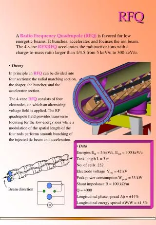
RFQ Beam Dynamics Design
RFQ Beam Dynamics Design. Basic RFQ vane profile with RFQ bunching. Transverse dimensions are magnified compared with longitudinal. Beam goes from left to right. Four sections: Radial Matching, Shaper, Gentle Buncher, Accelerator Section with changing cell geometry .


RFQ Beam Dynamics Design
E N D
Presentation Transcript
Basic RFQ vane profile with RFQ bunching • Transverse dimensions are magnified compared with longitudinal. • Beam goes from left to right. • Four sections: Radial Matching, Shaper, Gentle Buncher,Accelerator Section withchanging cell geometry. • Bunching is started in the Shaper. Adiabatic bunching (slow changes compared with the longitudinal oscillation period) is done in Gentle-Buncher section. • Accelerator section typically maintains approximately constant synchronous phase and vane modulation.
Example vane profile showing the four RFQ beam dynamics sections- This is a 2-MeV 100-mA 80-MHz D+ RFQ for neutron production.
Radial matching of a continuous or DC beam into the RFQ • Matching of a continuous or DC beam into the RFQ presents a special problem. • The matched ellipse parameters vary with the rf phase (or time) and are the same along the RFQ. • One needs to provide a transition from a beam with time independent characteristics to one that has the proper variations with time. • The solution is to taper unmodulated vanes at the RFQ input so that the radius decreases and the focusing strength increases from near zero to its full value over a distance of a few cells. Quadrupole symmetry is maintained throughout the RM section.
Radial Matching section for matching a continuous beam into the RFQ • First, the matched ellipse parameters are found in the interior cells of the RFQ for different phases 90 degrees apart. These look very different. • The ellipses at different phases tracked backwards to the input look very similar with a high degree of overlap. That is what we want. • To obtain the best approximate beam match, the average of these ellipses is taken to be the matched ellipse at the input. • Since x-x’ and y-y’ look almost identical, the matched input beam to the RFQ is nearly axisymmetric. • If the ion source beam is axisymmetric, solenoids or triplets could be used for matching in the low energy beam transport (LEBT). • For non-axisymmetric beams, quadrupole doublets can be used for beam matching into the RFQ.
Beam envelope at phases 90 degrees apart in a Radial Matching section. Three matched phase-space plots (x-x’ and y-y’) for phases 90 degrees apart are shown on the upper right. The phase space plots at the upper left show the same ellipses tracked backwards through the tapered RM section. The lower plot shows the beam profiles. Radial matching from K. Crandall using program TRACE.
Crandall’s radial matching section • Uses a four-term potential function • Satisfies Laplace’s equation • Each potential term is zero at end wall • Each potential term has physically reasonable s-shaped z dependence with zero at end wall and maximum at RFQ first cell. • Longitudinal electric field is zero at the end wall and zero at first RFQ cell. • Four equations in four unknowns are solved for four unknowns to get isopotential surface of RFQ vane profile.
The RFQ can adiabatically bunch a continuous beam beginning with m=1, but can also be designed to accelerate a prebunched beam. • For a prebunched input beam the RFQ could begin with an m>1 accelerator section. • Prebunched beams have a smaller range of phases (maybe ~60 deg or less) than for continuous beams. • You can match for the average phase and have good matching for all phases. No need to worry about matching for a continuous beam. • For a prebunched input beam, a RM section would not be necessary for matching. • However, if we start abruptly with m>1 the vanetip radii at the ends would not be equal and there would be an undesirable electric potential on axis. This can be corrected by adding a transition cell, to be discussed later.
RFQ adiabatic bunching is important for maintaining good beam quality in high current beams. • Bunching of high-current DC using rf cavities upstream of the linac increases the injected beam density causing space-charge-induced emittance blowup at high currents. • K-T proposed adiabatic bunching with minimal compression of the beam density, avoiding the emittance blowup from space charge. • But adiabatic bunching was not practical before the RFQ was invented, since it requires many longitudinal oscillation periods to gradually change the parameters, which requires a lot of real estate. • Length of the adiabatic bunching section ~ b3. So you need small b to shorten it. • The RFQ allows adiabatic bunching within a practical length, by providing strong-focusing at low-velocities, which lowers the injection energy.
Adiabatic bunching description • The objective is to produce acceleration and high capture efficiency of the incident DC beam without longitudinal beam compression. • Inject beam at low energy, typically 30 to 100 keV for protons. • Initial accelerating field is zero (no initial vane modulation). • Initial synchronous phase = -90 degrees,* where the bucket has 360 deg phase acceptance. This allows beam capture at all input phases. • Gradually increase the vane modulation to increase the accelerating field. • Gradually increase the cell-to-cell spacings to move the synchronous phase towards the crest of the accelerating field. *In linac convention the crest of the accelerating wave is at 0 deg, and phases for acceleration and longitudinal stability range from -90 to 0 deg.
K-T approach to adiabatic bunching for high-currents • As the beam is accelerated, the bunch phase length shrinks, but the bunch spatial length in centimeters can remain nearly constant. • Constant spatial bunch length avoids the large space-charge force from longitudinal compression that is associated with conventional bunching.
Adiabatic bunching determines A and fs as function of bs. • In linear region, the product of longitudinal oscillation frequency times the squared bunch length is an adiabatic invariant. This implies • Product of separatrix phase length Y times synchronous velocity is held constant. Controls bunch size in nonlinear region.
Example vane profile with adiabatic bunching in the gentle-buncher section. The shaper is a prebuncher that linearly ramps phase and vane modulation.
RFQ beam-current limit formulas are the basis of high current RFQ design • For RFQ designs of high-current beams one needs to provide an adequate beam-current limit in the design process.The Physics: • RFQ beam current is limited by the strength of the electric focusing • Focusing must compensate for space charge and must confine beam to within the available aperture. • Both transverse and longitudinal current limits can be calculated from the RFQ parameters, based on 3D ellipsoid model for the space-charge field. • Current Limit References:T.P.Wangler, “RF Linear Accelerators”, John Wiley&Sons 2nd Ed. (2008) pp.301-302.T.P.Wangler, Space Charge Limits in Linear Accelerators, Los Alamos Report LA-8338 (1980).
RFQ Beam Dynamics Movie • This shows beam dynamics of the RFQ. • Horizontal scale is exaggerated. • Viewed from rest frame of a bunch. The vanes are moving. • Notice that after bunch is formed the bunch physical length remains approximately constant, consistent with the design objective.
Special sections for input and output of the RFQ • Radial matching section is typically 4 to 6 cells long, has a flared vane profile, and can be used at either input or output of the RFQ. • Dm transition cell can be used at either input or output to smoothly transition from m=1 to m>1 or from m=>1 to m=1. • m=1 section has pure quadrupole symmetry, and arbitrary length. Its Iength can be chosen to adjust the output transverse phase space ellipses
Input radial matching section • Input Radial Matchingsection provides transverse matching for a continuous (DC) input beam between the space-periodic low-energy transport line and the time-periodic RFQ. • Crandall showed that radial matching works by gradually increasing the quadrupole focusing strength, done by reducing the aperture over a distance of about 4 to 6 RFQ cells.A converging input beam is required. • A converging vanetip profile with pure quadrupole symmetry is also required.
Beam envelope at phases 90 degrees apart in a Radial Matching section. Three matched phase-space plots (x-x’ or y-y’) for phases 90 degrees apart are shown on the upper right. The phase space plots at the upper left show the same ellipses tracked backwards through the tapered RM section. The lower plot shows the beam profiles.
Output radial matching section • Output radial matching section has a flared-out vane profile and can be used at the end of the RFQ vanes, where it eliminates an axial on-axis output potential. • Also, output phase space ellipses for both x-x’ and y-y’ can be made identical (same Courant-Snyder parameters) after beam expansion in the output radial matching section. This is good for matching into an output solenoid channel. • An output radial matching section allows matching to a periodic transport channel after the RFQ for both H+ and H- beams.
RFQ transition cell (K. Crandall*) is very useful for either the entrance and exit of the RFQ. First we discuss the RFQ exit. • For an RFQ where the vanes end abruptly at the end of the last accelerating cell, the unequal spacing of the vanetips causes a time-varying on-axis potential at the end and undesirable output beam-energy variation. • Consequently, Crandall introduced a new type of cell called the transition cell which makes a smooth transition from a full modulation (m>1) to pure quadrupole symmetry (m=1). • * K.R.Crandall, Ending RFQ Vane Tips With Quadrupole Symmetry, • Proc. 1994 Linac Conf., Tsukuba, Japan, (Aug 21-26, 1994)pp.227-229.
Vane-tip profiles from the RFQ two term potential function for constant m>1. The RFQ acceleration cells with unequal aperture spacing and nonzero on-axis potential and field.
Now add Crandall’s transition cell for ending RFQ vanes with pure quadrupole symmetry. This avoids unwanted energy change at the RFQ exit Vane-tip profiles in final accelerating cell (left) with m>1 Is followed by a Dm transition cell (right) which ends RFQ vanes in pure quadrupole symmetry with m=1
Transition cell (continued) • The transition cell is described by a special three-term potential solution to Laplace’s equation. • Crandall matches the potential and first two derivatives at the interface between the two cell types. • The length of the transition cell is slightly less than bl/2 length of the last accelerating cell:
Transition cell can also be used at the RFQ entrance for acceleration of a prebunched beam • The RFQ can be designed to accelerate a prebunched beam which has a limited phase length. The beam doesn’t need to be adiabatically bunched in the RFQ. • You can use a transition cell going from m=1 to m>1 to avoid an on-axis potential at the entrance.
RFQ transition cell at the entrance • If you start RFQ with an m>1 accelerator section, the lack of quadrupole symmetry means there is a time-varying on-axis potential at the input, which produces an undesirable time-dependent energy change at the input. • The on-axis potential at the input is eliminated by beginning the RFQ with an entrance transition cell which starts the RFQ with pure quadrupole symmetry (m=1) and transitions smoothly in one transition cell to the desired m>1. • The entrance transition cell is then followed by the first m>1 accelerating cell.
fout=0 fout=90 fout=180 fout=270 m=1 section • The m=1 section is an optional section with unmodulated vanes (quadrupole symmetry) that can follow a exit transition cell. • The length of the m=1 cell may be chosen to provide the desired RFQ output transverse ellipse orientation. • The ability to vary the phase of the output provides flexibility to facilitate matching at the RFQ exit. Examples are shown for different output phases on the right.
MSU Re-accelerator 4-Rod RFQ is being designed and built.Beam dynamics by MSU, construction by U. of Frankfurt. • Input energy: 12 keV/u • Output energy: 600 keV/u • Trans. Emitt = 0.6 p-mm-mrad • Long. Emitt = 0.3 p ns-keV/u • Frequency: 80.5 MHz • Length: 3.5 m • Transmission: ~ 82% • Room temperature structure • On order from U. of Frankfurt(Alwin Schempp) • Delivery: ~Fall 2009 31
The ISIS Four-Rod RFQ at Rutherford Appleton Laboratory35 keV to 665 keV H- beam, 202.5 MHz, V=90 kV showsa four-rod internal structure 32
The MSU reaccelerator RFQ will look similar to this CW 4-rod for SARAF (Soreq applied research accelerator facility in Israel).4 mA D+, CW, 3MeV, 176 MHz, 3.8 M , 220 kW, 39 cells. 33
SARAF 4-ROD RFQ – 4-mA D+ to 3 MeV, 176 MHz, 3.8 m long, 250 kW power 39 cells Tuning plates, shown between the stems, are for flattening the voltage distribution. 34
Rough Details on 4-Rod RFQ for MSU (Some of this may need to be updated.) • Copper-plated steel for rods (short vanes) and stems, and an aluminum tank and Copper plating done at GSI. • 20% to 30% of power losses are on the rods. Outer tank has about 5% of losses. Stems and tuning plates between the stems have the rest. • ~90 kV maximum intervane voltage. • Stems are bolted to tank. • Q~4000. • L~3.5m • RF power ~ 150 kW for 90 kV on vanes and 3.5 m rod length. One power coupler in the middle of RFQ. • Uses shims to align rods. Rods aligned to 100 microns. • Rods, stems, and outer tank are all water cooled. • Rods are water cooled separately from stems since because they determine the capacitance, they have a big effect on resonant frequency. • Water-cooled tuning plates between stems are independently positioned for achieving flat voltage profile. Intervane voltage profile uniform to 2.5% . • Uses square tank instead of cylindrical tank because of better delivery time, 10 mo. • Vacuum will require about two 500 liter/sec turbopumps provided by MSU. 35
RFQ Beam Dynamics Features of MSU four rod RFQ • The input beam is prebunched with a multiharmonic buncher (3 frequencies to approximate a sawtooth) instead of using adiabatic bunching within the RFQ. Prebunching shortens the RFQ. • Transition cells at entrance and exit are used to provide proper transition from non-quadrupole symmetry at ends of a normal RFQ accelerating cell with m~2 to quadrupole symmetry with m=1. Transition cells reduce undesirable axial fields at entrance and exit gaps. • Input end consists of a radial matching section followed by a transition cell. Output end consists of a transition cell followed by a radial matching section. These radial matching sections provide x-y symmetric phase space ellipses needed for matching to the external solenoid lenses. 36
Beam Dynamics Features of MSU RFQ design • A question still under study is whether the nonzero potential on axis caused by the nonsymmetric stem configuration at the ends of 4-rod RFQ causes any problems. Schempp believes this is a small effect. 37
Peak surface fields and RF electric breakdown are important topics for the RFQ
Kilpatrick Criterion on RF Breakdown • About 40 years ago, W. D. Kilpatrick analyzed the data on rf breakdown, and proposed the conditions that would avoid rf breakdown. • The results were expressed by T.J.Boyd in a convenient formula: where f is the frequency, and EK is called the Kilpatrick limit. The equation must be solved iteratively for EK. • The criterion is based on experimental results that were obtained in an era before clean vacuum systems were prevalent. The criterion is conservative by today's standards.
• To apply the Kilpatrick criterion to modern normal-conducting • structures, Boyd introduced the bravery factor. Replace Es=EK by • Es=b EK , where Es is the peak surface electric field, and b is • the bravery factor. • • Typical values range from 1.5<b<2.0. CW RFQs are usually • designed using less than about b=1.8. Larger values (b>2) may be used for pulsed accelerators with pulse lengths less than 1 msec. • • Notice EK increases with increasing frequency. Below 1 GHz, one finds approximately • For the RFQ Es=kV/r0 where k=1.25 to 1.55, depending on geometry and is 1.36 for circular vanetip cross section. Bravery Factor Modification
MSU Re-accelerator 4-Rod RFQ is being designed and built.Beam dynamics by MSU, construction by U. of Frankfurt. • Input energy: 12 keV/u • Output energy: 600 keV/u • Trans. Emitt = 0.6 p-mm-mrad • Long. Emitt = 0.3 p ns-keV/u • Frequency: 80.5 MHz • Length: 3.5 m • Transmission: ~ 82% • Room temperature structure • On order from U. of Frankfurt(Alwin Schempp) • Delivery: ~Fall 2009 43
Rough Details on 4-Rod RFQ for MSU (Some of this may need to be updated.) • Copper-plated steel for rods (short vanes) and stems, and an aluminum tank and Copper plating done at GSI. • 20% to 30% of power losses are on the rods. Outer tank has about 5% of losses. Stems and tuning plates between the stems have the rest. • ~90 kV maximum intervane voltage. • Stems are bolted to tank. • Q~4000. • L~3.5m • RF power ~ 150 kW for 90 kV on vanes and 3.5 m rod length. One power coupler in the middle of RFQ. • Uses shims to align rods. Rods aligned to 100 microns. • Rods, stems, and outer tank are all water cooled. • Rods are water cooled separately from stems since because they determine the capacitance, they have a big effect on resonant frequency. • Water-cooled tuning plates between stems are independently positioned for achieving flat voltage profile. Intervane voltage profile uniform to 2.5% . • Uses square tank instead of cylindrical tank because of better delivery time, 10 mo. • Vacuum will require about two 500 liter/sec turbopumps provided by MSU. 44
SARAF four-rod RFQ is the first four rod RFQ designed for CW (100%) duty operation. MSU four rod RFQ will be the second one.
The MSU reaccelerator RFQ will look similar to this CW 4-rod for SARAF (Soreq applied research accelerator facility in Israel).4 mA D+, CW, 3MeV, 176 MHz, 3.8 M , 260 kW, 39 cells. 46
SARAF 4-ROD RFQ – 4-mA D+ to 3 MeV, 176 MHz, 3.8 m long, 260 kW power 39 cells Tuning plates, shown between the stems, are for flattening the voltage distribution. 47
Beam commissioning • Operating in pulsed mode for beam commissioning with average power < 200W, limited by beam diagnostics. • Beam current measured in LEBT before the RFQ (Faraday cup) and also in MEBT after the RFQ (modular parametric current transformer). • Output ion energy measured with time of flight with two MEBT BPMs used as phase pickups. Also Rutherford scattering monitor from thin gold foil target for beam energy measurement. • Longitudinal bunch width measured with two Fast Faraday cups located downstream of RFQ.
High RF power commissioning for SARAF four-rod RFQ • The main challenge is removing 250 kW from the 3.8-m rods, an unprecedented heat density. A high-flow water-cooling system including flow inside the rods is incorporated. • A common RF conditioning procedure is to gradually raise the RF power at low duty factor, keeping the vacuum pressure below about 10-6 torr. • Then gradually increase duty factor. This allows RF conditioning while limiting risk of arcing damage on rods.
High RF power performance status* • What performance has the SARAF RFQ achieved? -Design power for deuterons is 260 kW • RF conditioning for about two months after opening up for the first time last year. Since then: -Achieved: 280 kW at 15% duty factor-Achieved: 240 kW CW for 30 min-Achieved: 210 kW CW for 2 hr -Achieved: 190 kW CW for 12 hours. • But recent field-emission problems and melting of a tuning plate forced them to open up for a second time. I. Mardor et al. “Status of the SARAF CW 40 MeV Proton/Deuteron Accelerator” , PAC2009, Vancouver, to be published.