FETS RFQ Beam Dynamics Simulations for RFQSIM, CST and Comsol Field Maps
140 likes | 378 Vues
FETS RFQ Beam Dynamics Simulations for RFQSIM, CST and Comsol Field Maps. Simon Jolly 2 nd June 2010. RFQ Field Map Comparisons. We now have 3 consistent methods of producing field maps for the RFQ: RFQSIM (from coefficients). CST (optimised field from August 2009).

FETS RFQ Beam Dynamics Simulations for RFQSIM, CST and Comsol Field Maps
E N D
Presentation Transcript
FETS RFQ Beam Dynamics Simulations for RFQSIM, CST and Comsol Field Maps Simon Jolly 2nd June 2010
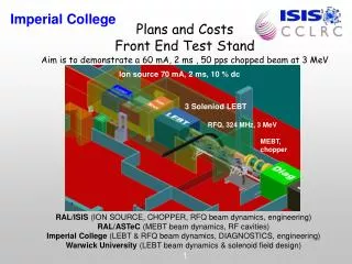
RFQ Field Map Comparisons • We now have 3 consistent methods of producing field maps for the RFQ: • RFQSIM (from coefficients). • CST (optimised field from August 2009). • Comsol (just finished in time for IPAC’10). • IPAC’10 RFQ beam dynamics paper: “Integrated Design Method And Beam Dynamics Simulations For The Fets Radiofrequency Quadrupole” • Needed to compare beam dynamics simulations for all 3 field mapping methods. • Simulations in GPT to compare CST and Comsol with 2 types of RFQSIM field (approximated and full). • Vary current between 0-120mA and measure transmission and final energy spread. Simon Jolly, Imperial College
Input Conditions • Current variation from 0-120mA; bunch length: 1RF period; SCtree3D space charge simulates bunched beam. • Using same input distribution as for previous publications: • xmax = ymax = 2.2mm. • x’max = y’max = 90mrad. • erms = erms = 0.25 p mm mrad. Simon Jolly, Imperial College
Field Map Differences • Differences between RFQSIM approximated and full fields at 5% level: • Smooth variation of coefficients between cells. • Full Bessel functions rather than truncated series. • CST uses maximum mesh density (4,700 points) with 6 RFQ sections (matching section, 2x500mm, 3x1m). • Comsol uses same vane model but not yet using tangential boundaries. • All field maps use 0.5mm point spacing (RFQSIM field maps match CST and Comsol, but different from previous simulations). Simon Jolly, Imperial College
Results: RFQSIM 2008 Transmission Energy Spread (60mA) Simon Jolly, Imperial College
Results: RFQSIM 2010 (Simple) Transmission Energy Spread (60mA) Simon Jolly, Imperial College
Results: RFQSIM 2010 (Full) Transmission Energy Spread (60mA) Simon Jolly, Imperial College
Results: CST Transmission Energy Spread (60mA) Simon Jolly, Imperial College
Results: CST Transmission Energy Spread (60mA) Simon Jolly, Imperial College
Preliminary Conclusions • RFQSIM simple field gives very similar results to old simulations: this is good! Differences probably due to GPT interpolation since point spacing is different. • RFQSIM simple and full fields also give very similar transmission results: • 92% transmission at 60 mA for both. • Full field expansion gives slightly higher final energy. • CST and Comsol also give very similar results, both for transmission and energy. But… Simon Jolly, Imperial College
Poor CAD Model Transmission • CST and Comsol give significantly poorer transmission than RFQSIM for higher beam currents. • Why the difference? Poor meshing or real RFQ properties? • Try increasing the field strength by up to 30% to see if we can recover transmision… Simon Jolly, Imperial College
Increased Field Strength • 10% increase in field strength recovers transmission: we’re back in business! • Is such an increase feasible in reality? Does it compare to known RFQ’s? • Not yet sure of the origin of this difference: might be mesh-based, might be real. Simon Jolly, Imperial College
Conclusions • Lots of results that make sense (a turn-up for the books!): • Simple and Full RFQSIM field maps show virtually no difference: slightly better RF capture and acceleration from Full field gives higher final energy. • CST and Comsol give very similar results: looks like we’re producing the same map through the same method. • Clear differences between CAD-based methods and RFQSIM: • Field strength nominally correct, since no extra transverse losses. • Longitudinal fields give problems: poor RF capture and acceleration. • But we can recover transmission by increasing the field strength: maybe field is closer to reality? • Longitudinal vane curvature certainly more subtle than transverse: need better mesh longitudinally. • Perhaps try a single Comsol simulation with very high mesh density (200mm RFQ sections) and see if transmission improves at 60mA. • Should we start optimising on “realistic” beam? Simon Jolly, Imperial College