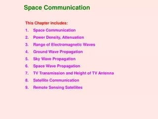
Free Space Optical Communication
Free Space Optical Communication. Picture: http://www.cablefreesolutions.com/index.htm. ‘Wireless’ Optics?. Picture: http://www.cablefreesolutions.com/index.htm. Fiber replaced by free space Channel characteristics not in control Transmitter and Receiver essentially the same

Free Space Optical Communication
E N D
Presentation Transcript
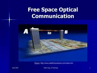
Free Space Optical Communication Picture: http://www.cablefreesolutions.com/index.htm Mohit Garg, IIT Bombay
‘Wireless’ Optics? Picture:http://www.cablefreesolutions.com/index.htm • Fiber replaced by free space • Channel characteristics not in control • Transmitter and Receiver essentially the same • Indoor and Outdoor implementations differ • Three basic configurations • Line of Sight (max. bandwidth) • Directed -- Non-Line of Sight Hybrid • Non directed -- Non-Line of Sight Diffused (min. bandwidth) Thus ‘Wireless’ need not imply Roaming Mohit Garg, IIT Bombay
Indoor links… Picture:Optical Wireless- The Promise and Reality , Heatly and Neild • Interference • Incandescent Light (~ 2800 K) – Max. interference • Sunlight (~ 6000 K) • Fluorescent lamps • Attenuation • Free Space Loss (due to beam divergence) --important • Atmospheric Loss (not much indoors) • Eye Safety – Most Important • Should be class I safe (< 0.5 mW, 880 nm, LASER) • Restricts system power (though LEDs can be used at higher powers, but Bandwidth limited) Mohit Garg, IIT Bombay
Outdoor links… Picture: http://www.cablefreesolutions.com/imagelib21.htm • Attenuation – Most Important • Atmospheric Loss (varies with weather) • 0.2 dB/km in exceptionally clear weather • 300 dB/km in very dense fog • Restricts the range (~500m in most commercial systems) • May need low capacity back-up RF links • Free Space Loss (due to beam divergence) • Scintillation Noise (atmospheric turbulence induced intensity fluctuations) – speckled pattern • Alignment Issues – Line of sight • Interference • Sunlight (~ 6000 K) Mohit Garg, IIT Bombay
Attenuation :: Outdoor links PR= PT . Areceiver . e –σ.R/(Div-range)2 PR ~ PT e –σ.R • Free Space losses beam divergence • Atmospheric losses exponential term– dominates • Scattering + Absorption • Scattering dominates in σ Does Attenuation depend on wavelength? Mohit Garg, IIT Bombay
Attenuation ::Scattering Depends on particle size • Size parameter α = 2π r/λ • ‘ r ’ varies with atmospheric composition r << λ => σ ~ λ-4 Rayleigh Scattering r ~ λ => σ ~ λ-1.6 to 0Mie Scattering r >> λ => σ ~ λ0 Geometric Scattering Thus, larger λ => lower attenuation Belief that 1550 nm is less attenuated than 785 nm in fog. Does this apply always? Mohit Garg, IIT Bombay
Attenuation ::Scattering …contd Table:Comparison of beam propagation in haze and fog, Kim, McArthur and Koreevar The authors, studied the FOGGY weather conditions which were showing a discrepancy between analytical and empirical data. Mohit Garg, IIT Bombay
Attenuation ::Scattering …contd • The particle size distribution is difficult to obtain. so we express in terms of Visibility (V) σ= (3.91/V) x (λ/550 nm)-q V= visibility (km) light falls off to 2% of initial value q= Size distribution of scattering particles = 1.6 (V>50 km) = 1.3 (6 km <V< 50 km) = 0.16 V+0.34 (1 km <V< 6 km) Haze = V - 0.5 (0.5 km <V< 1 km) Mist = 0 ( V < 0.5 km) Fog The authors, proposed a new wavelength dependence through Mie Scattering calculations Earlier = 0.585 V1/3 (V < 6 km) Mohit Garg, IIT Bombay
Scintillation Noise Inhomogenities in Temp. and Pressure Variations in Refractive Index along the transmission path Speckled pattern (both in time and space) at the receiver Can be removed by time and space averaging. But problems arise with restrictions on size of receiver and high bit rates. Mohit Garg, IIT Bombay
Some images Pictures: http://www.cablefreesolutions.com/imagelib.htm Mohit Garg, IIT Bombay
Web Resources • www.freespaceoptic.com • www.cablefreesolutions.com/casestudies.htm • www.engalco.co.uk/fso_report.htm • www.fiberwork.com.br/site/english/fso_e.htm • www.ieeexplore.ieee.org Mohit Garg, IIT Bombay