Download
1 / 31
310 likes | 508 Vues
Building Blocks for Mobile Free-Space-Optical Networks. Jayasri Akella, Chang Liu, David Partyka, Murat Yuksel, Shiv Kalyanaraman , and Partha Dutta Rensselaer Polytechnic Institute Emails: sri@networks.ecse.rpi.edu, yuksem@ecse.rpi.edu. : “ shiv rpi ”. Outline. Context and Motivation

E N D
Building Blocks for Mobile Free-Space-Optical Networks Jayasri Akella, Chang Liu, David Partyka, Murat Yuksel, Shiv Kalyanaraman, and Partha Dutta Rensselaer Polytechnic Institute Emails: sri@networks.ecse.rpi.edu, yuksem@ecse.rpi.edu : “shiv rpi”
Outline • Context and Motivation • Auto-configurable optical antenna design. • Tessellated Spherical Optical Antenna • Auto-alignment Circuit • Mobility Experiment • Simulating Mobile FSO Networks • Results and summary
Free-Space-Optical Communications (FSO) Ad Hoc Networking High bandwidth Low power Directional Mobile communication Auto-configuration Free-Space-Optical Ad Hoc Networks Spatial reuse and angular diversity in nodes Low power and secure Electronic auto-alignment Optical auto-configuration (switching, routing) Bringing Optical Communications and Ad Hoc Networking Together… This paper proposes initial building blocks for this vision…
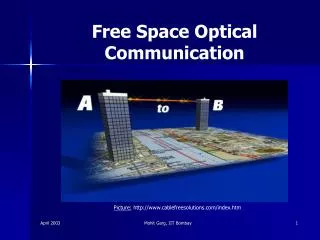
Current Commercial FSO Point-to-Point Links in dense metros, competing with “wires” and “leased lines” Issues: How to achieve link reliability/availability despite weather
Current RF-Based Ad Hoc Networks • 802.1x with omni-directional RF antennas • High-power – typically the most power consuming part of laptops • Low bandwidth – typically the bottleneck link in the chain • Error-prone, high losses
Contributions: Ad-hoc FSO BBlocks • New optical antenna design • Spherical/Honeycomb structure with FSO trans-receiver modules • Potential: logical links function even when antennas are in relative motion. • Auto-configuration circuit that enables physical FSO channel handoff • Integrated with optical antenna design • Simulation models in ns-2 to enable future studies of FSO MANETs • Initial tests suggest need to revisit routing and TCP layer designs
FSO Basics • High-brightness LEDs (HBLEDs) are very low cost and highly reliable components • 35-65 cents a piece, 10 years lifetime • Low power consumption (100 microwatts for 10-100 Mbps!) • 4-5 orders of magnitude improvement in energy/bit compared to RF • Directional => Huge spatial reuse • But…FSO also requires: • availability of unobstructed line-of-sight (LOS) and, • alignment of LOS between the transmitter and the receiver.
LED P D LOS Alignment: Optical Antenna Concept • Tessellated spheres with trans-receiver pairs • Line-of-sight (LOS) auto-alignment electronics • Rapid alignment & handoff => enables mobility or sway, while maintaining the logical link. • Tessellated Sphere b) Showing a Line of Sight Sphere • Tessellated with LED+PD transceivers.
Auto-Alignment Circuit Design • Pilot signal sent • If aligned, signal is fed-back • Feedback signal detection => alignment! • Handoff logical link & transmit data
Optical antenna: Multiple Alignment Circuits • Multiple channels => • Connected to a bank of auto-alignment circuits • Eg: 4-circuit block diagram shown below
Optical antenna: Experimental Platform (Contd) • LEDs: high divergence angle • PDs: angular field of view => the LED-PD pair forms a transceiver cone. • The transceiver cone covers a significant volume of 3-dimensional space. • Key: appropriate packing density to cover entire 360 steradian of surrounding space. Tessellated Spherical antennas on stable optical testing platforms
In Action: 4-channel spherical optical antenna Not Aligned: Searching phase to locate an LOS (all channels searching) Aligned: Data Transmission phase (only one channel active)
Mobility Experiment • UDP data transfer between the moving toy train on a circular track and a data-sink at the center of the circle.
Intensity vs Mobility @ The optical antenna Aligned Not aligned Detector Threshold Denser packing will allow fewer interruptions (and smaller buffering), but more handoffs
Simulation Model: Mobile Ad-Hoc FSO nodes • NS-2 Model: • FSO propagation model (weather effects) • FSO antennas (sphere model) • Additional parameters: • directional normals, transmission and receiving angles • … to assist the propagation model and LOS calculations.
Mobile FSO Simulation (Contd) • Initial proof-of-concept: • 2-D scenario on the XY-plane • Spatial reuse and angular diversity features illustrated. • Single mobile FSO node • Circles around four stationary FSO nodes • Stationary nodes are connected via wired links to a single central node.
Simple Experiments… • Four experiments, varying: • Speed of mobile node and • Distance of the mobile node from the central node
Experiment 2: Higher distance => TCP interactions & lower throughput
Experiment 3: Lower distance, higher speeds TCP affected by higher loss rates & periodic disconnections
Observations • Need dense tessellation and packing. • Need rapid auto-alignment • TCP may be affected with increasing distance and speed. • End-to-end connection is not the same as physical link alignment • Key: • Need to provide either bit-level buffering and/or • Link-layer hybrid ARQ/FEC to mask such losses from TCP • Interactions with transport and network level protocols will need to be studied and optimized… • Ongoing work…
Summary • Ad-hoc FSO communication: • Different from pt-pt FSO and ad-hoc RF • Key building blocks: • Optical antenna: tessellated sphere with dense packing of trans-receivers • Auto-Alignment optoelectronic circuit (simple feedback design) • Absence of mechanical parts such as motors or moving mirrors typically used for auto-alignment purpose. • Significant savings in power consumption and improved alignment reliability. • Simple demonstration: optical data transmission between toy train and ground nodes • NS-2 simulation components: • FSO propagation models • Mobile FSO antennas. • Initial simulation: points to need for optimizing interactions w/ transport and network level protocols.
Thanks! Students: Jayasri Akella, sri@networks.ecse.rpi.edu Dr. Murat Yuksel (post-doc): yuksem@ecse.rpi.edu Chang Liu, c.liu@ee.unimelb.edu.au David Partyka, partyd@rpi.edu Sujatha Sridharan : “shiv rpi” Ps: Online free videos of all my advanced networking classes
Simulation of mobile FSO nodes continued • An FTP session is kept alive between the central node and the mobile node. For our experiments, all wired links are 100 Mbps with 2ms delays and Drop Tail queues, while the FSO nodes are configured to only transmit at 20 Mbps. (20Mbps is just our configuration limitation, and is not a physical limitation as modulation speeds can be in the order of GHz in optical bands) • Initially, the experiment starts with the mobile node and one of the stationary nodes in LOS. • Soon after the session is established, the node moves around the stationary nodes at a constant rate of speed. Routing is performed by ad hoc DSDV routing agents and MAC is facilitated by 802.11 that is already present in NS-2.
Simulation of mobile FSO nodes continued • We can see that using FSO propagation model in the simulation, it is possible to achieve connectivity through mobile FSO communication even with a very small number of transceivers on the spherical optical antenna. • The experiments were configured in such a manner that LOS is not always present, thus showing that connectivity is reestablished when the nodes are back in LOS. This is demonstrated by the periods of inactivity in the utilization graphs and by the plateaus in the TCP sequence number graphs, which is shown in the figure. • The TCP sequence numbers for the other experiments also showed similar behavior, where plateaus exist for connectivity periods. • Furthermore, increase in the TCP sequence numbers imply that: • All simulation components from physical layer to transport layer are setup properly, thereby provides validity of our simulation building blocks. • Transport level good-put can be achieved over a highly variant (i.e. frequent LOS changes) FSO environment.