Download
1 / 108
1.2k likes | 2k Vues
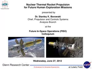
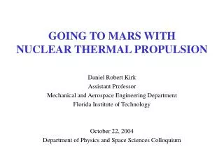
GOING TO MARS WITH NUCLEAR THERMAL PROPULSION. Daniel Robert Kirk Assistant Professor Mechanical and Aerospace Engineering Department Florida Institute of Technology October 22, 2004 Department of Physics and Space Sciences Colloquium. GOING TO MARS WITH NUCLEAR THERMAL ROCKET PROPULSION.

E N D
GOING TO MARS WITHNUCLEAR THERMAL PROPULSION Daniel Robert Kirk Assistant Professor Mechanical and Aerospace Engineering Department Florida Institute of Technology October 22, 2004 Department of Physics and Space Sciences Colloquium
GOING TO MARS WITH NUCLEAR THERMAL ROCKET PROPULSION • Comments from President Bush (January 2004) • “Our third goal is to return to the Moon by 2020, as the launching point for missions beyond.” • “With the experience and knowledge gained on the Moon, we will then be ready to take next steps of space exploration: Human missions to Mars and to worlds beyond.” • A human mission to Mars implies need to move large payloads as rapidly as possible, in an efficient and cost-effective manner • Renewed interest in break-through deep space science/exploration missions • Project Prometheus and Jupiter Icy Moon Orbiter (JIMO)
OVERVIEW • Rocket Overview • Categorization of various types of Rockets • Rocket Mission Selection Guide • Rocket Performance Parameters • Nuclear Thermal Propulsion • Historical Overview • Hot Hydrogen Properties • Fluid Mechanic and Heat Transfer Modeling • Simulation Results • Future Work – What can we do at FIT? • How to Simulate Nuclear Reactors for Space Applications • New Experimental Facility • Analytical and Computational Efforts
WHY ROCKET PROPULSION? • Rockets provide means to: • Insert payloads into space (satellites, experiments, defense applications, etc.) • Space exploration (Atmospheric, solar system) • Precise, continuous or pulsed, momentum change (station keeping) • Weapons (wide range of missiles: cruise 1st stage boost, ICBM) • Rapid change in momentum devices (retro-rockets, JATO, car air bags) • Rockets vs. other propulsion devices • Advantages: orbital insertion, deep space travel, etc. • Disadvantages: carry all propellant, small payload fraction (STS ~ 0.01) • Area of vigorous research and development • Rocket propulsion is an exact, but not a fundamental subject • No basic scientific laws of nature peculiar to propulsion
ROCKET CLASSIFICATION • Rockets may be classified in many ways • Depending on energy source (chemical, electrical, nuclear, etc.) • Depending on gas acceleration mechanism / force on vehicle mechanism • Basic function (booster, sustainer, station keeping) • Type of vehicle (missile, aircraft, spaceship) • Based on performance measures (T, T/W, Isp, h) and/or propellant types • By number of stages • Primary distinction between Chemical (thermal) and Electrical systems • Only types of rockets in operation today • However, a future human mission to Mars will likely utilize a NEW version of an OLD concept: Nuclear Thermal Propulsion
HOW A CHEMICAL ROCKET WORKS F Chemical Energy Rocket Propulsion (class of jet propulsion) that produces thrust by ejecting stored matter • Propellants are combined in a combustion chamber where chemically react to form high T&P gases • Gases accelerated and ejected at high velocity through nozzle, imparting momentum to engine • Thrust force of rocket motor is reaction experienced by structure • Same phenomenon which pushes a garden hose backward as water flows from nozzle QUESTION: Could a jet or rocket engine exert thrust while discharging into a vacuum (with not atmosphere to “push against”)? Thermal Energy Kinetic Energy
NUCLEAR PROPULSION: PROJECT ORION • 1955 (classified paper) release atomic bombs behind a spacecraft • Bombs would explode, creating a hot plasma, which would them push against a spacecraft pusher plate, propelling it forward • Interstellar version: called for a 40-million-ton spacecraft to be powered by the sequential release of ten million bombs, each designed to explode roughly 60 m to vehicle's rear • Nuclear test-ban treaty: explosion of nuclear devices illegal “This is the first time in modern history that a major expansion of human technology has been suppressed for political reasons."
ADVANCED PROPULSION TECHNOLOGIES • Solar sailing is a method of converting light energy from the sun into a source of propulsion for spacecraft • Obtain propulsive power directly from Sun • No Engine → No Need to Carry Fuel • Photons are reflected off giant, mirror-like sails made of thin, lightweight, reflective material • Continuous pressure exerted by photons provide thrust • Very high Isp • Open up new regions of solar system for exploration, with no environmental impact on Earth • Leading candidate for missions that require spacecraft to hold position in space, rather than orbit Earth or Sun • May also extend duration of other missions • Light Sails Do NOT harvest the solar wind for their propulsion (solar wind < 0.1% due to that of light pressure) • Do not convert to electricity like solar cells
MOMENTUM EXCHANGE TETHERS • Momentum-eXchange/Electrodynamic-Reboost (MXER) tether is combination of technologies designed to help propel satellites and spacecraft • Long, strong cable rotating in an elliptical orbit around Earth • Like a catapult, one end of tether catches payloads in LEO, accelerates them to higher velocities, and then throws them into higher-energy orbits • Momentum to payload restored using ED forces to push against Earth’s B field • Solar power drives ionospheric current, tether reboost without using propellant
WHAT IS ENERGY LIMIT? “The basic secret of space travel and extending human presence throughout heliocentric space is energy, immense quantities of energy”
ANTIMATTER PROPULSION • Propulsion by annihilation of matter and antimatter is under investigation • Mixture of matter/antimatter provides highest energy density of any propellant • Most efficient chemical reactions produce about 1 x 10⁷ J/kg, nuclear fission 8 x 10¹³ J/kg, and nuclear fusion 3 x 10¹⁴ J/kg, complete annihilation of matter and antimatter, E = mc2, yields 9 x 10¹⁶ J/kg • Matter-antimatter annihilation releases about ten billion times more energy than H2/LOX mixture that powers SSME and 300 times more than fusion reactions at Sun's core • Antimatter must be manufactured • 1 gram of antimatter ~ $62.5 trillion • Isp ~ 10,000,000 s • Mars in 2 hours = 1/10th gram antimatter
EVERYTHING YOU NEED TO KNOW TO BE A ROCKET SCIENTIST • Thrust, [N] • “How much Force?” • T/W is key metric for launch vehicles • Less important with space exploration applications • Specific Impulse, [sec] • “How Efficient?” • High thrust (chemical) have low specific impulse • High specific impulse (electric) rockets usually have low thrust • Increasingly important for space exploration applications • Increases with increasing temperature and decreasing molecular weight • Ideal Rocket Equation, [m/s] (1 form of many) • “When and How Fast? Can a rocket travel to a speed faster than speed at which exhaust leaves rocket?
OUTLINE • Rocket Overview • Categorization of various types of Rockets • Rocket Mission Selection Guide • Rocket Performance Parameters • Nuclear Thermal Propulsion • Historical Overview • Hot Hydrogen Properties • Fluid Mechanic and Heat Transfer Modeling • Simulation Results • Future Work – What can we do at FIT? • How to Simulate Nuclear Reactors for Space Applications • New Experimental Facility • Analytical and Computational Efforts
WHY NUCLEAR THERMAL PROPULSION? • NTP improvement: 100-400 percent over best conventional rocket motors • Large gain in DV, Isp possible with NTP rockets • Operate for short time ~ 1-3 HRS to achieve desired DV • Highly reduced mission times (12-14 months vs. 2-3 years to Mars) • Combination of temperature and low molecular weight: Isp ~ 900 s (2 x SSME)
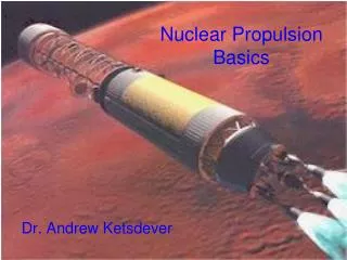
RD-0410 Nuclear Thermal Engine BACKGROUND: REVIEW OF PROGRAMS (1955-PRESENT) • Rover/NERVA, GE-710, ANL (1955-1973) • Soviet Union (195?-1986) • SDI (1983-1988) • SEI (1989-1993) • INSPI (UF) /LUTCH (1993-1997) • INSPI (1992-Present)
ROVER/NERVA HISTORY • Main objective of Rover/NERVA (Nuclear Engine for Rocket Vehicle Application) was to develop a flight-rated thermodynamic nuclear rocket engine • Initially program and engine designed for missile applications • 1958: NASA use in advanced, long-term space missions • Reactor Tests: • Kiwi-A, Kiwi-B, Phoebus, Pewee, and the Nuclear Furnace, all conducted by Los Alamos to prove concepts and test advanced ideas • Rocket Engine Tests: • Aerojet and Westinghouse tests: NRX-A2 (NERVA Reactor Experiment), A3, EST (Engine System Test), A5, A6, and XE-Prime (Experimental Engine). • Conducted at Nuclear Rocket Development Station at AEC's Nevada Test Site • Late 1960's and early 1970's, Nixon Administration cut NASA and NERVA funding cut dramatically and ultimately project ended in 1973
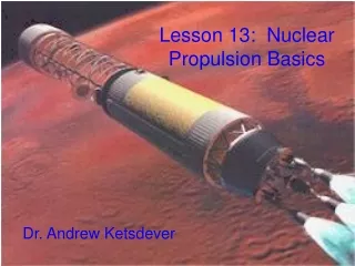
NTP BASIC OPERATION • NTP rockets utilize fission energy to heat a reactor core to high temperatures • Monopropellant H2 coolant/propellant flowing through core becomes superheated and exits engine at very high exhaust velocities
NUCLEAR-FUEL MATERIALS • Uranium – “The mother of all nuclear fuels” • Uranium ‘found’ in 1727, ‘discovered’ as a unique, half-metal in 1789 • Concept of nuclear fission first introduced in 1939 • U3O8: U234, U235, U238 • Pu239 (may also be formed from U238) • Th232 (→ U233) Note: BLUE: fissionable fuel, RED: source material • Fuel is highly enriched (90-99% U235 present) • Most important properties: Nuclear properties (cross sections, particle behavior, burn up), physical, thermal, mechanical, chemical (hot H2) effects) • About 10 billion nuclear fuel atoms undergoing fission / cm3-sec in reactor core • May be varied to control Temperature very acutely • Fission process is independent of propellant/coolant flow 600,000 pounds of chemical fuel = 1 pound of nuclear fuel
THERMAL GENERATION MECHANISM: NUCLEAR FISSION Various coolants may be used: H2O, Ar, He, liquid metals, H2 Total Radiation Exposure Mission to Mars: NTP < Chemical Rocket
IF NTP SO GOOD, WHY HASN’T IT HAPPENED? “Sounds too much like Buck Rogers!”, President Eisenhower (1958) “The day is not far off when nuclear rockets will prove feasible for space flight.” (1965) • “Chicken and egg syndrome" • “It takes longer to develop a NTP system than to develop a space mission. Project managers cannot include NTP systems in mission planning until system has been developed and tested.” • “If only reactors could be developed, users would emerge to claim them.” • “NTP ready for flight tests and yet no users have come forward in ensuing decades.” • “Cutbacks were made in response to a lack of public interest in human space flight, end of space race, and growing use of low-cost unmanned, robotic space probes.” • "Post Vietnam Congresses appear more concerned with perceived excesses of science and technology, hence their abolishment of [NTP] and space committees.” • “Cynical maneuvering, vicious attacks and double dealing that led to its closing after years of toil to prove the successful development of then Project Rover/NERVA in 1973.” • “They pushed NASA hard because it was dominated by people who built there lives around chemical rockets they didn't want to see [nukes] come in cause they feared it.”
IF IT’S NOT NEW… WHAT IS THERE TO DO? • Fuel sets upper limit of NTP performance • “No fuel geometry or material ever totally solved NERVA fuel degradation problem.” • “Mass loss limits life by causing significant perturbation to core neutronics.” • “Crack development in fuel element coating was never completely eliminated.” • “Non-nuclear testing of coated elements revealed relationship between diffusion and temperature. For every 205 K increase, mass loss increased by factor of ten.” • Limited experimental data at temperature, temperature ratio, heat flux, L/D for H2 • “Correlations have not been verified experimentally at heat flux levels present in coolant channels and accuracy and applicability of these equations is in question.” • “Even though Re, Pr, L/D within stated range of accuracy for existing correlations, Tw/Tbulk ratio exceeds range of database if heat flux is high enough.” "One overriding lesson from NERVA program is fuel and core development should not be tied simply to a series of engine tests which require expensive nuclear operation. Definitive techniques for fuel evaluation in loops or in non-nuclear heated devices should be developed early and used throughout program..."
RESEARCH CONTEXT A well thought out and carefully designed NTP roadmap is needed • NTP is well investigated technology, but development / improvement remains • Heat transfer relations, geometries, materials, etc. • Fuel development and evaluation essential component of NTP program • Testing at max temperatures, heat fluxes, transients, duration, re-start, etc. • Preliminary Research Programs are Beginning to Form • Non-Nuclear development to gain knowledge base • Design of experiment, data acquisition and analysis • Partnering to facilitate development • Confluence of NASA, industry (P&W), and academia • Hot H2 NTP experiments at MSFC • Support / design / build-up from academia
APPROACH • Non-nuclear testing in hot H2 environment key to engine development • T=300-3200 K • Realistic mass flow rates (0.8-1.5 g/s per) and inlet pressures (500 psi) • Modular test section: investigate NERVA, particle bed, pebble bed, etc. • Materials characterization and assessment of performance/stability in hot H2 • Safety, instrumentation, diagnostics, etc. “The Rover/NERVA engine is to be used as a “reference,” against which other concepts… will be compared.” - Dr. Stanley K. Borowski “Solid core has plenty of growth potential. Just because it's 1960's era technology doesn't mean it's obsolete. Object of a new program should be to build on this.” “If you had kept on working [NERVA] you would now have a 4th generation system. It would have Isp's over 1000, power densities 3000 MW, and maybe 30 hours of engine lifetime with 180 stop & starts.” - Dr. James Dewar, AEC
RANGE OF NTP INPUT DATA Summary: Baseline Case Values Power / Fuel Element ~ 1MW / Element for each case Flow Rates ~ 1.5 g/s H2 Chamber Pressure ~ 3.5 MPa (~ 500 PSI) Maximum Propellant Temperature ~ 2500 K
REACTOR TEMPERATURE DISTRIBUTION MODEL Model: Single H2 cooling passage within single element Test sub-section to replicate various portions of cooling path Match power input, H2 temperature and wall temperature at various x/D, r/D locations Cooling Hole ID: 0.1-0.125 inches / Cooling Holes OD: 0.183 inches L/D ~ 500 for NERVA elements
H2 COOLANT / PROPELLANT COMMENTS • Range of interest • T=300-3000 K, P=14.7-1000 psi • Important to model H2 properties accurately • Up to ~ 1500 K, pressure has little effect on Cp, g, m, k • For T > 1500 K, must include pressure effect on thermal transport properties • References: NASA SP [King],[Kubin and Presley],[Weber], [McCarty], [Patch] • Dissociation with P at constant T • P=1 ATM, T=3000 K, NH=15 % vs. P=40 ATM, T=3000 K, NH=2.6 % • Isp improvement with dissociation, but no impact on cf • Ionization: not relevant at these temperatures • P=1 ATM, T=3000 K, NH+ ~ O(10-11) vs. P=40 ATM, T=3000 K, NH+ ~ O(10-12) • Compressibility: small effect • P=1 ATM, T=3000 K, Z=8.2 % vs. P=40 ATM, T=3000 K, Z=1.3 %
H2 COMMENTS: UNIQUE BEHAVIOR P=1 ATM, T=2600 K NH=3.9 %, NH+=1.3x10⁻¹³ P=40 ATM, T=2600 K NH=0.6 %, NH+=8.8x10⁻¹⁵ Effects of dissociation and ionization on cp, k are dramatic Higher pressures dissociation suppressed NTP “nominal” range of operation T < 3500 K and P ~ 20-40 ATM
H2 COMMENTS: VACUUM SPECIFIC IMPULSE Phoebus 2A, Ispvac~918 s Vacuum Isp equation corrected for dissociation Isp based on channel exit temperature, not mixed-out temperature Mixed-out temperature (model) ~ 100-300 K lower than exit temperature, 10% Isp
H2 COMMENTS: DISSOCIATION AND ISP,VAC As Pch, mass flow , Thrust (T/W) System optimization for required T/W vs. Isp, future work consideration Max material (U,Zr,Nb)C temperature ~ 3300 K (1hr): Max Tmelt (TaC, HfC) ~ 4200 K
HYDRODYNAMIC CONSIDERATIONS/MODELING • Laminar and Turbulent Regions, critical Reynolds numbers • ReD ~ 2,300 onset of turbulence • ReD ~ 10,000 for fully turbulent conditions • ReD ~ 70,000 for Phoebus/NERVA • Entrance and fully developed region • No satisfactory general expression for entry length in turbulent flow • Fully-developed turbulent flow for x/D > 20 (approx. independent of ReD) • Pressure drop and inlet/exit boundary conditions • Total pressure decrease due to constant volume heat addition (~7 %) • Thermal choking: Only 1/3rd of total DTt,max/Tt capacity • H2 attack on core / degradation • Corrodes/erodes away channel wall and protective coatings, “Scouring” action • Radial pressure drops (channel to channel) which shakes core modules • Mass loss and cracking of elements
TEMPERATURE DISTRIBUTION: COMMENTS • Note that Tbulk maximum at L=100% • Maximum inner and centerline wall temperatures at L ~ 80% • For metals, Re, Ta, W, TCL and TID close ~ 50 K • For actual NTP materials, TCL and TID exhibit larger DT ~ 100-500 K • For actual NTP materials, TCL and TID not at same axial location • Location of maximum Twall-Tbulk, Axial Twall, Axial Tbulk all located in mid-band region • Mid-band region of max corrosion from NERVA reports: • "Corrosion most pronounced in mid-range region, about a third of distance from cold end” • “Fuel operating temperatures lower here than fabrication temperatures, hence thermal stresses higher than at hot end. Also, neutron flux highest in this region..." • Flow time ~ 6 ms, Velocities ~ 1000 m/s at exit, but M ~ 0.2 • 55 kW to single cooling channel for H2 simulation
HEAT TRANSFER COEFFICIENT: VARIOUS FORMS • Various heat transfer correlations may be applicable within operational range • Differ by up to 20% (not to mention H2 data uncertainty) • Correlations at such elevated conditions, “that do exist have not been verified experimentally at the heat flux levels present in coolant channels and accuracy and applicability of these equations is in question.”
HEAT TRANSFER EXPERIMENTAL SCALING • Convective coefficient scales with diameter as hg~1/D0.2 • Doubling tube diameter will decrease hg by 13% • Smaller diameters lead to larger heat fluxes (from Reynolds dependence on Cf) • Heat flux almost linear with pressure, scales as hg~r0.8~p0.8 • Halving inlet pressure will reduce coefficient by 57% • Lighter gases lead to higher heat fluxes, hg~1/M0.6 • Ratio of molecular weights of Ar:H2 ~ 20, heat flux for Ar:H2 ~ 16% • Evaluation of viscosity term is also important both at wall and fluid temperatures • Accounts for differences in gas temperature within boundary layer and bulk flow • Exponent less than unity, acts as enhancement of heat transfer coefficient • Careful evaluation of cp, m, k
OVERVIEW • Rocket Overview • Categorization of various types of Rockets • Rocket Mission Selection Guide • Rocket Performance Parameters • Nuclear Thermal Propulsion • Historical Overview • Hot Hydrogen Properties • Fluid Mechanic and Heat Transfer Modeling • Simulation Results • Future Work – What can we do at FIT? • How to Simulate Nuclear Reactors for Space Applications • New Experimental Facility • Analytical and Computational Efforts
BUILD-UP OF EXPERIMENT • Surrogate test gases to build-up experiment in less-complex, cost effective way • H2 and hot H2 logistics and safety precautions • Reduced power requirements • Development with bench-top 12.5 kW induction system • Verification of experimental set-up, diagnostics, heat transfer correlations • Reduced cost elements (Ta) vs. materials ~ 100% dense to H2 (Re) • Make use of surrogate test gases, such as He, N2, and Ar • Investigate cooling channel using 12.5 kW power supply • Using Ar, test entire elements (19 cooling channels) at PRL using 100 kW • Using surrogate test gases, match: • Non-dimensional and actual temperatures • Heat fluxes • Heat transfer coefficients • Scale power input, mass flow, gas type, etc.
SURROGATE TEST GASES: He, N2, Ar H2 He N2 Ar