Download
1 / 17
190 likes | 549 Vues
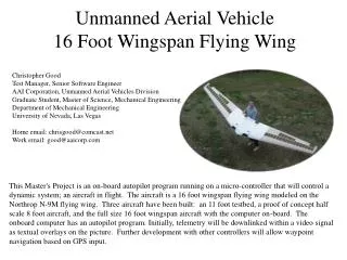
Unmanned Aerial Vehicle 16 Foot Wingspan Flying Wing. Christopher Good Test Manager, Senior Software Engineer AAI Corporation, Unmanned Aerial Vehicles Division Graduate Student, Master of Science, Mechanical Engineering Department of Mechanical Engineering University of Nevada, Las Vegas

E N D
Unmanned Aerial Vehicle16 Foot Wingspan Flying Wing Christopher GoodTest Manager, Senior Software EngineerAAI Corporation, Unmanned Aerial Vehicles DivisionGraduate Student, Master of Science, Mechanical EngineeringDepartment of Mechanical EngineeringUniversity of Nevada, Las Vegas Home email: chrisgood@comcast.netWork email: good@aaicorp.com This Master's Project is an on-board autopilot program running on a micro-controller that will control a dynamic system; an aircraft in flight. The aircraft is a 16 foot wingspan flying wing modeled on the Northrop N-9M flying wing. Three aircraft have been built: an 11 foot testbed, a proof of concept half scale 8 foot aircraft, and the full size 16 foot wingspan aircraft with the computer on-board. The onboard computer has an autopilot program. Initially, telemetry will be downlinked within a video signal as textual overlays on the picture. Further development with other controllers will allow waypoint navigation based on GPS input.
Flying Wing UAV Control Surfaces Elevons Drag rudders (each wingtip) Power Twin Ducted Fans OS .65 VR-DF engine Turbax III fan unit Flight Control NetMedia BasicX-24 micro-controller Sensors Analog Devices ADXL-202 accelerometer Nanotron NA070 tilt sensors Motorola pressure transducers Hall-effect sensors & PIC event counters Upgraded Flight Control NewMicros ISOPOD
Prototype & Construction Half size prototype This plane was built and test flown to prove the airfoil and airframe were stable. An OS 46 engine and tractor propeller provide power. No drag rudders are on this airframe and it is controlled only by remote control. Full size construction Wing tips (6’ each) plug in to the center section, which holds computers, sensors, engines, fuel, RC gear, batteries.
Avionics The attitude sensors were supplied for free as test units; Analog Devices supplied the ADXL-202 accelerometers and Nanotron supplied the NA-070 tilt sensors. NA-070 tilt sensors Leads to computer serial RS-232 connector NetMedia BasicX-24 ($40) Motorola MPX-4115A pressure sensor for altitude ($20) 0-65k feet ADXL-202 accelerometer Motorola MPX 2010G low pressure sensors for airspeed ($10 for three) 0-1.3 psi, 0-705 mph Infra-red remote receiver for short range (<5 ft) control ($5) 9 volt power
Ground Control Station JR Radio Compaq Laptop Collinear Antenna WIT2410 RF SERIAL (2) Trainer Signal 2.4 GHz Down-converter Noteworthy PCMCIA Video Capture Collinear Antenna Gameport to USB Converter RC to PC Gameport Converter USB Gameport Autopilot and Navigation Flight with RC Backup Ground control of the ISOPOD will be done via a WIT2410 RF modem transceiver identical to the airborne unit. The video signal will be down-converted to a base-band composite signal and captured for display on the laptop by the PCMCIA video capture card. This eliminates the need for a separate TV to view airborne video. Manual control of the aircraft will be done with a JR radio. The analog stick movements are converted to the standard JR digital trainer box signal. This digital signal is converted to the standard PC analog gameport signals, and finally converted to a USB signal for input to the laptop. RF Modem Datalink The datalink will done with Cirronet WIT2410 2.4GHz spread spectrum wireless industrial transceivers. These plug into the serial ports of the computers at each end of the link and are invisible to the serial connection. They transmit at 100mW and frequency hop to any one of 64 preprogrammed patterns.
BasicX-24 Sensors Analog ADXL202 Roll Analog ADXL202 Pitch Remote Control Receiver Piezo gyro Roll rate DIGITAL (2) Piezo gyro DIGITAL (2) Pitch rate Dipole Antenna DIGITAL (1) Antenna Data Acquisition, Display Nanotron NA070 Tilt Sensor DIGITAL (1) Roll Video Transmitter DIGITAL (1) uBlox GPS SERIAL (1) BasicX-24 DIGITAL (1) Nanotron NA070 Tilt Sensor Pitch BOB-II Video Overlay SERIAL (1) ANALOG (1) MPX2010G Pressure Sensor Camera ANALOG (1) Airspeed (x 16) MPX4115A Pressure Sensor Altitude Data Gathering Flight with RC Control Only Initial testing will include data acquisition only; data will be displayed to the controlling PC on the ground and via the BOB-II video overlay module in the air. GPS data is displayed only. Analog input is converted with an 8 channel, 10 bit ADC.
BasicX-24 Sensors Analog ADXL202 Roll Serial Servo Controller (SSC) Analog ADXL202 Pitch Remote Control Receiver Safety MUX Piezo gyro Roll rate DIGITAL (2) Piezo gyro SERIAL (1) DIGITAL (2) Pitch rate Dipole Antenna DIGITAL (1) Antenna Data Acquisition, Display, Autopilot Nanotron NA070 Tilt Sensor DIGITAL (1) Roll Video Transmitter DIGITAL (1) uBlox GPS SERIAL (1) BasicX-24 DIGITAL (1) Nanotron NA070 Tilt Sensor Pitch BOB-II Video Overlay SERIAL (1) ANALOG (1) MPX2010G Pressure Sensor Camera ANALOG (1) Airspeed (x 16) MPX4115A Pressure Sensor Altitude Autopilot Flight with RC Backup After data acquisition flights, autopilot control will be added. This is inner loop control: straight and level flight at a preset airspeed. GPS data is displayed only. The SSC, safety MUX, and autopilot inner loop software are added here.
ISOPOD Sensors Analog ADXL202 Roll Analog ADXL202 Pitch Piezo gyro Remote Control Receiver Safety MUX Roll rate DIGITAL (2) Piezo gyro DIGITAL (2) Pitch rate DIGITAL (1) MPX2010G Pressure Sensor Dipole Antenna Alpha Antenna Data Acquisition, Display, Autopilot, Navigation DIGITAL (1) ANALOG (1) Video Transmitter uBlox GPS MPX2010G Pressure Sensor SERIAL (1) ANALOG (1) Beta ISOPOD BOB-II Video Overlay ANALOG (1) SERIAL (1) MPX2010G Pressure Sensor ANALOG (1) Airspeed SERIAL(2) Camera DIGITAL (1) WIT2410 RF Dipole Antenna (x 16) MPX4115A Pressure Sensor DIGITAL (1) Altitude Autopilot and Navigation Flight with RC Backup The ISOPOD has much greater capabilities than the BasicX-24. It has dedicated PWM servo outputs and I/O counters, and will be able to handle all navigation tasks by itself. Analog input is converted with an 8 channel, 12 bit ADC. Hall Effect Sensor Tachometer L/R Hall Effect Sensor
Sensors Accelerometers: Analog Devices ADXL202, 2 axix, 2-g accelerometers. Rate Gyros: Murata Piezo rate gyroscope. I bought a non-working Gyropoint mouse on eBay, cheap. By gutting the mouse and removing the piezo gyro daughterboard, I have two rate gyros already soldered onto a board and ready to use. Tilt Sensors: Nanotron NA-070 electrolytic tilt sensors, 0 –70 degree range. Altitude: Motorola MPX 4115A, ~1 – 15 psi, 0-65k feet Vout to measure 0-4000 feet 10 bit ADC -> 4 ft resolution 12 bit ADC -> 1 ft resolution (x 16) Non-inverting Amplifier Gain = 16 = 1+(RB/RA) = 1 + (1.5M/100K) = (x 16)
Airspeed Sensors & Pitot Tube Mathematics Airspeed: Motorola MPX 2010G, 0-1.3 psi, 0-705 mph 10 bit ADC -> 705/1024 = .68 mph 12 bit ADC -> 705/4096 = .17 mph I needed to determine what the maximum pressure the pressure transducer would experience in flight, so I could buy the right sensor for airspeed sensing. The pressure in the ram section of a pitot tube is comprised of two components, the dynamic and the static. Because most pressure transducers sense the difference between some input and static (gauge pressure), we only need to look at the dynamic pressure exerted by the moving air. Dynamic fluid pressure is defined as: P(dynamic) = 0.5 (r) (v2) , where v = velocity of fluid (air), r = density of fluid (air) r(air) @ sea level, incompressible (low Mach number) = 1.229 kg/(m3) We will assume a max velocity of 50 m/s (111 mph). So we get: Pmax=.5 (1.229 kg/(m3)) (50 m/s)2 = 1536.25 kg/(m s2) We need to convert this to PSI. To do that, we need to convert kg to pounds(force), which is different from pounds(mass). Remember the Mars Observer satellite? It went splat because NASA forgot to convert pounds(force) to pounds(mass). 1 pound(mass) = .4535 kg 1 pound(force) = 32.174 pound(mass) ft/sec2 (multiplied by gravity at sea level) 1 ft = .3048 meter 1 ft2 = 144 in2 After all these numbers are put in the equation, we get: P(dynamic, air) = 32 pound(force) / ft2 @ 111 mph = .22 pound(force) / in2 @ 111 mph = .22 psi @ 111 mph So, to measure airspeed up to 111 mph, we need a pressure transducer that can read at least .22 psi. I have three Motorola MPX2010G pressure transducers that are rated at 1.4 psi. They should work up to 318 m/s or 705 mph (in an incompressible flow, which at 705 mph is not true, but anyway...) No problem.
Video Downlink Video Downlink A Pixera mini camera ($26) will take video. It feeds into a Decade Engineering BOB-II video overlay module ($85) that accepts commands via a serial line. The output of that feeds into a Comtech 100mW 2.4Ghz PLL controlled RF module ($45). The RF module is controlled by a PIC ($12) that selects the frequency based on dip-switch settings. The RF module feeds directly into a dipole antenna, built from plans found on the internet. A commercial X-10 2.4 GHz receiver ($25) will be used to down-convert the video signal for display on a standard television. I will use a omnidirectional collinear vertical stacked dipole antenna built from plans found on the internet.
BOB-II Video Overlay Bob-II overlays 28 columns x 11 rows of white text with a black border. Everything underlined is updated; all else is static. Air sensor data and attitude data are updated as fast as the micro-controller can process the sensor inputs. GPS data and tachometers are updated at 1 Hz. A XXX mph = air data airspeed (mph) XXXXX ft = air data altitude (ft) L XXXXX RPM = left tach (rpm) R XXXXX RPM = right tach (rpm) (Analog accelerometers) P XX U/D = pitch in deg, up/down R XX R/L = roll in deg, right/left (Nanotron tilt sensors) P XX U/D = pitch in deg, up/down R XX R/L = roll in deg, right/left hh:mm:ss = GPS Time G XXX mph = GPS ground speed (mph) dd:mm:ss N/S = GPS latitude HD XXX deg = GPS heading (deg) XXXXX ft = GPS altitude (ft) ddd:mm:ss E/W = GPS longitude
Servo Control Serial Servo Controller (SSC) A Scott Edwards Electronics SSC ($29) accepts commands via a serial line and can control up to 8 servos.
GPS Trimble-Lassen SK8 Trimble-Lassen LP uBlox PS1 GPS Receivers The Trimble SK8 (5.0 volts power, $35) and LP (3.3 volts power, $25) each monitor 8 satellites. The LP is a low power version of the SK8, and both receivers output NMEA or TSIP messages on serial port 1. The uBlox ($80) monitors 12 channels, and outputs NMEA or SIRF messages on serial port 1. All receivers accept RTCM-SC104 differential GPS corrections on serial port 2. GPS Antennas I decided to make my own active antenna using commercial components. The TOKO DAX1575MS63T ceramic patch element (18mm x 18mm) is $5 from AVNET. All of these receivers require an active antenna, which means this needs some type of low noise amplifier (LNA). After searching many homemade GPS antenna web pages, I found the M/A-COM AM50-00002 for $4 from MHz Marketing. M/A-COM AM50-00002 1.575 Ghz LNA TOKO DAX1575MS63T GPS CERAMIC PATCH ELEMENT
Controller Prototypes Ampro 286 miniboard. This single board computer ($40) with a 286 10MHz processor was the first board I picked to be the autopilot on-board computer. It has a small ISA backplane that can be attached for ground testing. More research has lead to the use of the smaller, lighter Flashlite V25+ single board computer. Flashlite V 25+. This single board computer ($40) with a 10MHz processor was the next board I picked to be the autopilot on-board computer. It runs a straight DOS 3.3 environment, has a 128KB flash hard drive, and lots of I/O. Continuous advances in hardware have left this board behind also, allowing the much smaller BasicX-24 and ISOPOD to be used. Additional Development Antenna Trimble LP Multiple GPS Receivers Further development may include multiple GPS receivers. All the Trimble units will be MUXed to a single serial port and replace the uBlox GPS. Antenna Trimble LP MUX Antenna Trimble SK8
Test Hardware The following pages show some miscellaneous hardware, and some equipment that I built for testing and other hardware configurations. For example, the ADC’s were going to be used for analog input before I decided on using the BasicX-24, which has its own 10 bit, 8 channel ADC. Analog Devices ADXL105’s. Each one measures 1 to 5 g’s in one axis. The small board on top is an op-amp acting as a data buffer. Analog-to-digital converter AD7812. 10 bit, 8 channels. I made this board with capacitors to smooth out the supply voltage (also the reference voltage), and a 7805 voltage regulator as the power supply. Analog-to-digital converter ADC0838. 8 bit, 8 channels. I added two micro potentiometers to channels 1 and 2 for testing. This board also has a 7805 voltage regulator as the power supply.
Test Hardware Rate Gyroscope. A Futaba G153BB rate gyro will be used to smooth out yaw oscillations via the drag rudders. I have an identical gyro in my RC helicopter and it works very nicely. Mercury Tilt Switches.Initial testing was done with a set of mercury tilt switches for absolute left/right roll, up/down pitch. It was built as a temporary input device for attitude input. This will not be used in the aircraft. They were acquired from a air-conditioning company (from old thermostats) for free. Printer Port Indicator.To verify the printer port interactions, I built this indicator device to show when the individual bits in the parallel port I/O area are on and off. The 5 push-button switches are used to manually simulate the data coming from an input device (A/D converter, for example). This was built from parts from Radio Shack and has been used for testing digital I/O with a PC’s parallel port.