Crystals
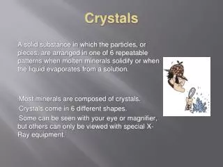
Crystals. Crystal Structures. Atoms (and later ions) will be viewed as hard spheres. In the case of pure metals, the packing pattern often provides the greatest spatial efficiency (closest packing).

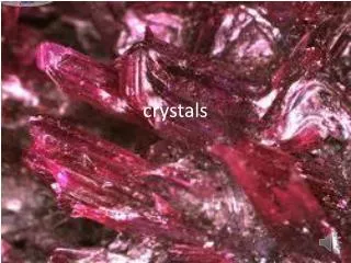
Crystals
E N D
Presentation Transcript
Crystal Structures Atoms (and later ions) will be viewed as hard spheres. In the case of pure metals, the packing pattern often provides the greatest spatial efficiency (closest packing). Ionic crystals can often be viewed as a close-packed arrangement of the larger ion, with the smaller ion placed in the “holes” of the structure.
Unit Cells Crystals consist of repeating asymmetric units which may be atoms, ions or molecules. The space lattice is the pattern formed by the points that represent these repeating structural units.
Unit Cells A unit cell of the crystal is an imaginary parallel-sided region from which the entire crystal can be built up. Usually the smallest unit cell which exhibits the greatest symmetry is chosen. If repeated (translated) in 3 dimensions, the entire crystal is recreated.
Close Packing Since metal atoms and ions lack directional bonding, they will often pack with greatest efficiency. In close or closest packing, each metal atom has 12 nearest neighbors. The number of nearest neighbors is called the coordination number. Six atoms surround an atom in the same plane, and the central atom is then “capped” by 3 atoms on top, and 3 atoms below it.
Close Packing If the bottom “cap” and the top “cap” are directly above each other, in an ABA pattern, the arrangement has a hexagonal unit cell, or is said to be hexagonal close packed. If the bottom and top “caps” are staggered, the unit cell that results is a face-centered cube. This arrangement is called cubic close packing.
Close Packing Either arrangement utilizes 74% of the available space, producing a dense arrangement of atoms. Small holes make up the other 26% of the unit cell.
Holes in Close Packed Crystals There are two types of holes created by a close-packed arrangement. Octahedral holes lie within two staggered triangular planes of atoms.
Holes in Close Packed Crystals The coordination number of an atom occupying an octahedral hole is 6. For n atoms in a close-packed structure, there are n octahedral holes.
Octahedral Holes The green atoms are in a cubic close-packed arrangement. The small orange spheres show the position of octahedral holes in the unit cell. Each hole has a coordination number of 6.
Octahedral Holes The size of the octahedral hole = .414 r where r is the radius of the cubic close-packed atom or ion.
Holes in Close Packed Crystals Tetrahedral holes are formed by a planar triangle of atoms, with a 4th atom covering the indentation in the center. The resulting hole has a coordination number of 4.
Tetrahedral Holes The orange spheres show atoms in a cubic close-packed arrangement. The small white spheres behind each corner indicate the location of the tetrahedral holes.
Tetrahedral Holes For a close-packed crystal of n atoms, there are 2n tetrahedral holes. The size of the tetrahedral holes = .225 r where r is the radius of the close-packed atom or ion.
# of Atoms/Unit Cell For atoms in a cubic unit cell: • Atoms in corners are ⅛ within the cell
# of Atoms/Unit Cell For atoms in a cubic unit cell: • Atoms on faces are ½ within the cell
# of Atoms/Unit Cell A face-centered cubic unit cell contains a total of 4 atoms: 1 from the corners, and 3 from the faces.
# of Atoms/Unit Cell For atoms in a cubic unit cell: • Atoms in corners are ⅛ within the cell • Atoms on faces are ½ within the cell • Atoms on edges are ¼ within the cell
Other Metallic Crystal Structures Body-centered cubic unit cells have an atom in the center of the cube as well as one in each corner. The packing efficiency is 68%, and the coordination number = 8.
Other Metallic Crystal Structures Simple cubic (or primitive cubic) unit cells are relatively rare. The atoms occupy the corners of a cube. The coordination number is 6, and the packing efficiency is only 52.4%.
Polymorphism Many metals exhibit different crystal structures with changes in pressure and temperature. Typically, denser forms occur at higher pressures. Higher temperatures often cause close-packed structures to become body-center cubic structures due to atomic vibrations.
Atomic Radii of Metals Metallic radii are defined as half the internuclear distance as determined by X-ray crystallography. However, this distance varies with coordination number of the atom; increasing with increasing coordination number.
Atomic Radii of Metals Goldschmidt radii correct all metallic radii for a coordination number of 12. Coord #Relative radius 12 1.000 8 0.97 6 0.96 4 0.88
Alloys Alloys are solid solutions of metals. They are usually prepared by mixing molten components. They may be homogeneous, with a uniform distribution, or occur in a fixed ratio, as in a compound with a specific internal structure.
Substitutional Alloys Substitutional alloys have a structure in which sites of the solvent metal are occupied by solute metal atoms. An example is brass, an alloy of zinc and copper.
Substitutional Alloys These alloys may form if: 1. The atomic radii of the two metals are within 15% if each other. 2. The unit cells of the pure metals are the same. 3. The electropositive nature of the metals is similar (to prevent a redox reaction).
Interstitial Alloys Interstitial alloys are solid solutions in which the solute atoms occupy holes (interstices) within the solvent metal structure. An example is steel, an alloy of iron and carbon.
Interstitial Alloys These alloys often have a non-metallic solute that will fit in the small holes of the metal lattice. Carbon and boron are often used as solutes. They can be dissolved in a simple whole number ratio (Fe3C) to form a true compound, or randomly distributed to form solid solutions.
Intermetallic Compounds Some mixtures of metals form alloys with definite structures that may be unrelated to the structures of each of the individual metals. The metals have similar electronegativities, and molten mixtures are cooled to form compounds such as brass (CuZn), MgZn2, Cu3Au, and Na5Zn2.
Ionic Compounds Since anions are often larger than cations, ionic structures are often viewed as a close-packed array of anions with cations added, and sometimes distorting the close-packed arrangement.
Common Crystal Types 1. The Rock Salt (NaCl) structure- Can be viewed as a face-centered cubic array of the anions, with the cations in all of the octahedral holes, or
Common Crystal Types 1. The Rock Salt (NaCl) structure- A face-centered cubic array of the cations with anions in all of the octahedral holes.
Common Crystal Types 1. The Rock Salt (NaCl) structure- The coordination number is 6 for both ions.
Common Crystal Types 2. The CsCl structure- Chloride ions occupy the corners of a cube, with a cesium ion in the center (called a cubic hole) or vice versa. Both ions have a coordination number of 8, with the two ions fairly similar in size.
Common Crystal Types 3. The Zinc-blende or Sphalerite structure- Anions (S2-) ions are in a face-centered cubic arrangement, with cations (Zn2+) in half of the tetrahedral holes.
Common Crystal Types 4. The Fluorite (CaF2) and Antifluorite structures A face-centered cubic arrangement of Ca2+ ions with F- ions in all of the tetrahedral holes.
Common Crystal Types 4. The Fluorite (CaF2) and Antifluorite structures The antifluorite structure reverses the positions of the cations and anions. An example is K2O.
Ionic Radii Ionic radii are difficult to determine, as x-ray data only shows the position of the nuclei, and not the electrons. Most systems assign a radius to the oxide ion (often 1.26Å), and the radius of the cation is determined relative to this assigned value.
Ionic Radii Like metallic radii, ionic radii seem to vary with coordination number. As the coordination number increases, the apparent ionic radius increases.
Ionic Radii 1. Ionic radii increase as you go down a group. 2. Radii of ions of similar charge decrease across a period. 3. If an ion can be found in many environments, its radius increases with higher coordination number. 4. For cations, the greater the charge, the smaller the ion (assuming the same coordination #). 5. For atoms near each other on the periodic table, cations are generally smaller than anions.
Predicting Crystal Structures General “rules” have been developed, based on unit cell geometry, to predict crystal structures using ionic radii. Radius ratios, usually expressed as the (radius of the cation)/(radius of the anion) are used.
Predicting Crystal Structures General “rules” have been developed, based on unit cell geometry, to predict crystal structures using ionic radii. Radius ratios, usually expressed as the (radius of the cation)/(radius of the anion) are used. This assumes that the cation is smaller than the anion.
Predicting Crystal Structures CNr+/r-accuracy 8 ≥0.70 quite reliable 6 0.4 -0.7 moderately reliable 4 0.2 –0.4 unreliable 3 0.10 -0.20 unreliable
Energetics of Ionic Bonds The lattice energy is a measure of the strength of ionic bonds within a specific crystal structure. It is usually defined as the energy change when a mole of a crystalline solid is formed from its gaseous ions. M+(g) + X-(g) MX(s)
Lattice Energy M+(g) + X-(g) MX(s) ∆E = Lattice Energy Lattice energies cannot be measured directly, so they are obtained using Hess’ Law. They will vary greatly with ionic charge, and, to a lesser degree, with ionic size.
1/2 bond energy of Cl2 Electron Affinity of Cl Ionization energy of K Lattice Energy of KCl ∆Hsub of K} ∆Hf of KCl
Lattice Energy Attempts to predict lattice energies are generally based on coulomb’s law: VAB = (Zae)(Zbe) 4πεorAB Za and Zb = charge on cation and anion e= charge of an electron (1.602 x 10⁻¹⁹C) 4πεo=permittivity of vacuum (1.1127 x 10⁻¹⁰J-1C2m-1) rAB = distance between nuclei
Lattice Energy Since ionic crystals involve more than 2 ions, the attractive and repulsive forces between neighboring ions, next nearest neighbors, etc., must be considered.