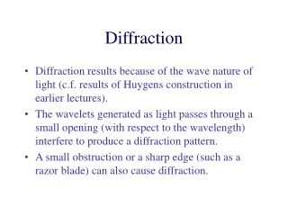
Diffraction
Diffraction. AP Physics B. Superposition ..AKA….Interference. One of the characteristics of a WAVE is the ability to undergo INTERFERENCE . There are TWO types. . We call these waves IN PHASE. We call these waves OUT OF PHASE. Diffraction.

Diffraction
E N D
Presentation Transcript
Diffraction AP Physics B
Superposition ..AKA….Interference One of the characteristics of a WAVE is the ability to undergo INTERFERENCE. There are TWO types. We call these waves IN PHASE. We call these waves OUT OF PHASE.
Diffraction When light OR sound is produced by TWO sources a pattern results as a result of interference.
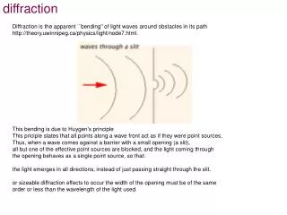
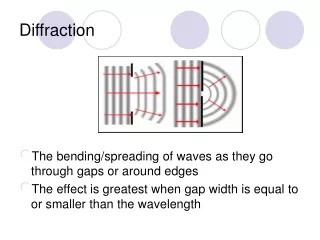
Interference Patterns Diffraction is normally taken to refer to various phenomena which occur when a wave encounters an obstacle. It is described as the apparent bending of waves around small obstacles and the spreading out of waves past small openings
Diffraction – The Central Maximum Suppose you had TWO sources each being allowed to emit a wave through a small opening or slit. The distance between the slits denoted by, d. The distance from the slit spacing to the screen is denoted by the letter, L. If two waves go through the slit and then proceed straight ahead to the screen, they both cover the SAME DISTANCE and thus will have constructive interference. Their amplitudes will build and leave a very bright intense spot on the screen. We call this the CENTRAL MAXIMUM.
Diffraction – The Central Maximum Figure 2 Figure 1 Here is the pattern you will see. Notice in figure 2 that there are several bright spots and dark areas in between. The spot in the middle is the BRIGHTEST and thus the CENTRAL MAXIMUM. We call these spots FRINGES. Notice we have additional bright spots, yet the intensity is a bit less. We denote these additional bright spots as ORDERS. So the first bright spot on either side of the central maximum is called the FIRST ORDER BRIGHT FRINGE. Figure 1 represents the intensity of the orders as we move farther from the bright central maximum.
Diffraction – Orders, m We use the letter, m, to represent the ORDER of the fringe from the bright central. Second Order Bright Fringe m = 2 Second Order Bright Fringe m = 2 First Order Bright Fringe m = 1 First Order Bright Fringe m = 1 Central Maximum It is important to understand that we see these bright fringes as a result of CONSTRUCTIVE INTERFERENCE.
Diffraction – Bright Fringes The reason you see additional bright fringes is because the waves CONSTRUCTIVELY build. There is a difference however in the intensity as you saw in the previous slide. As you can see in the picture, the BLUE WAVE has to travel farther than the RED WAVE to reach the screen at the position shown. For the BLUE WAVE and the RED WAVE to build constructively they MUST be IN PHASE. Here is the question: HOW MUCH FARTHER DID THE BLUE WAVE HAVE TO TRAVEL SO THAT THEY BOTH HIT THE SCREEN IN PHASE?
Diffraction – Path difference Notice that these 2 waves are IN PHASE. When they hit they screen they both hit at the same relative position, at the bottom of a crest. How much farther did the red wave have to travel? Exactly – ONE WAVELENGTH l The call this extra distance the PATH DIFFERENCE. The path difference and the ORDER of a fringe help to form a pattern.
Diffraction – Path Difference 2l 2l The bright fringes you see on either side of the central maximum are multiple wavelengths from the bright central. And it just so happens that the multiple is the ORDER. 1l 1l Therefore, the PATH DIFFERENCE is equal to the ORDER times the WAVELENGTH P.D. = ml (Constructive)
Diffraction – Dark Fringes We see a definite DECREASE in intensity between the bright fringes. In the pattern we visible notice the DARK REGION. These are areas where DESTRUCTIVE INTERFERENCE has occurred. We call these areas DARK FRINGES or MINIMUMS.
Diffraction – Dark Fringes First Order Dark Fringe m = 1 First Order Dark Fringe m = 1 ZERO Order Dark Fringe m = 0 ZERO Order Dark Fringe m = 0 Central Maximum It is important to understand that we see these dark fringes as a result of DESTRUCTIVE INTERFERENCE.
Diffraction – Dark Fringes On either side of the bright central maximum we see areas that are dark or minimum intensity. Once again we notice that the BLUE WAVE had to travel farther than the RED WAVE to reach the screen. At this point , however, they are said to destructively build or that they are OUT OF PHASE. Here is the question: HOW MUCH FARTHER DID THE BLUE WAVE HAVE TO TRAVEL SO THAT THEY BOTH HIT THE SCREEN OUT OF PHASE?
Diffraction – Path difference Notice that these 2 waves are OUT OF PHASE. When they hit they screen they both hit at the different relative positions, one at the bottom of a crest and the other coming out of a trough. Thus their amplitudes SUBTRACT. How much farther did the red wave have to travel? Exactly – ONE HALF OF A WAVELENGTH 0.5 l The call this extra distance the PATH DIFFERENCE. The path difference and the ORDER of a fringe help to form another pattern.
Diffraction – Path Difference 1.5l 1.5l The dark fringes you see on either side of the central maximum are multiple wavelengths from the bright central. And it just so happens that the multiple is the ORDER. 0.5l 0.5l Therefore, the PATH DIFFERENCE is equal to the ORDER plus a HALF, times A WAVELENGTH P.D. = (m+1/2)l (Destructive)
Path Difference - Summary For CONSTRUCTIVE INTERFERENCE or MAXIMUMS use: For DESTRUCTIVE INTERFERENCE or MINIMUMS use: P.D. = ml P.D. = (m+1/2)l Where “m”, is the ORDER. Refer to slides 7 and 12.
Young’s Experiment In 1801, Thomas Young successfully showed that light does produce an interference pattern. This famous experiment PROVES that light has WAVE PROPERTIES. Suppose we have 2 slits separated by a distance, d and a distance L from a screen. Let point P be a bright fringe. We see in the figure that we can make a right triangle using, L, and y, which is the distance a fringe is from the bright central. We will use an angle, q, from the point in the middle of the two slits. We can find this angle using tangent! P y q d B.C. L
Diffraction – Another way to look at “path difference” This right triangle is SIMILAR to the one made by y & L. P q q d B.C. d P.D. P.D. = dsinq P.D. Notice the blue wave travels farther. The difference in distance is the path difference.
Similar Triangles lead to a path difference y q d L These angles Are EQUAL. dsinq q
Diffraction – Putting it all together Path difference is equal to the following: • ml • (m+1/2)l • dsinq Therefore, we can say: Will be used to find the angle!
Example A viewing screen is separated from a double slit source by 1.2 m. The distance between the two slits is 0.030 mm. The second -order bright fringe ( m=2) is 4.5 cm from the central maximum. Determine the wavelength of light. 2.15 degrees 5.62x10⁻⁷ m
Example A light with wavelength, 450 nm, falls on a diffraction grating (multiple slits). On a screen 1.80 m away the distance between dark fringes on either side of the bright central is 4.20 mm. a) What is the separation between a set of slits? b) How many lines per meter are on the grating? 0.067 degrees 5197.2 lines/m 0.0001924 m