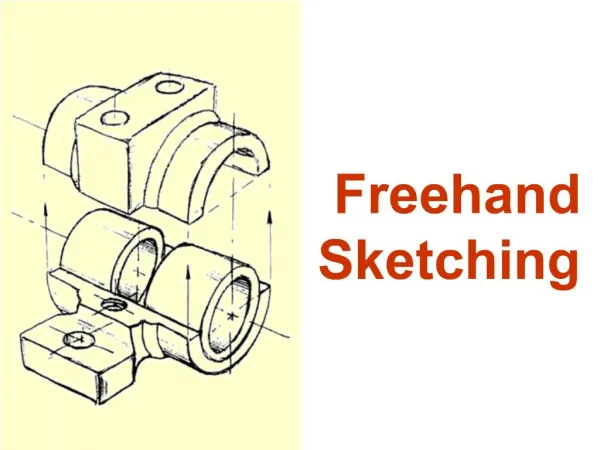
Freehand Sketching
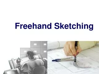
Freehand Sketching Introduction to Mechanical Engineering Fall 2004 Created by: P.M. Larochelle & J.S. Ketchel Freehand Sketching Ideation – Integral to the design process Generation of design concepts to solve a design problem

Freehand Sketching
E N D
Presentation Transcript
Freehand Sketching Introduction to Mechanical Engineering Fall 2004 Created by: P.M. Larochelle & J.S. Ketchel
Freehand Sketching • Ideation – Integral to the design process • Generation of design concepts to solve a design problem • Usually freehand sketching is used to explore, study and communicate these design concepts • Even today, and for the foreseeable future, many great design ideas are communicated via freehand sketching • The “BEST” design engineers can immediately communicate an idea via a freehand sketch
Freehand Sketching • Required • Pencil, Paper and Eraser • Do not use • Straight edges, templates, compasses etc. They slow down the process and defeat the purpose of fast communication of ideas!
Freehand Sketching • Sketches are planned • Visualize the sketch • Size of paper & scale • Orientation of the object • Minimum detail to communicate the idea • Type of sketch • Oblique • Isometric • Orthographic
Types of Sketches • Oblique • Advantage: one true face • Disadvantage: not “photorealistic” • Isometric (a type of axonometric drawing) & Perspective • Advantage: easy to visualize the object • Disadvantage: no true face • Multi-View (orthographic) • Advantage: true faces • Disadvantage: hard to visualize • Isometric, oblique, and perspective sketches are methods of showing the object in a single view.
Freehand Sketching • Freehand sketches are not sloppy!
Freehand Sketching • When possible use the grid on your engineering paper!
Freehand Sketching • Outline the sketch • Use light lines • Show major edges and boundaries and then add small details
Freehand Sketching • Shape the sketches • Add appropriate details • Darken object lines
Freehand Sketching • Fundamental Rule of Sketching • Maintain Proportion • Hints: use standard techniques to draw lines and arcs • Lines • Locate a start “dot” • Locate an end “dot” • Put pencil on start dot, look at the end dot and smoothly move pencil toward the end dot
Freehand Sketching • Circles (arcs) • Draw light horizontal and vertical lines that intersect at the center • Lightly mark the radius on the lines • Connect the radius marks with arcs to complete the circle • See Step-by-Step 3.1& 3.3 on pages 60 & 62.
Construction Lines • Light and thin lines • Serve as path for final straight lines • Intersection of construction lines specify the length of the final lines • Points marked by the intersection of construction lines serve as guides for sketching of arcs and circles • Guide the proportion of the sketch
Oblique Sketching • Step 1 – Draw the horizontal and vertical construction lines which outline the basic shape of the main face - “Blocking in” • Step 2 – Sketch the face of the part • Step 3 – Sketch receding construction lines at 30 or 45 degrees • Step 4 – Sketch- in and darken the lines outlining the part – Done!
Isometric Sketching • Step 1 – Construct a horizontal line, two lines at 30 degrees above the horizontal and a vertical line through their intersection • This defines the isometric axes used to draw the sketch
Isometric Sketching • Step 2 – Sketch in a box to “block-in” the front face and the other faces follow • Step 3 – Sketch the outline of the front face in it’s “block” and the other faces follow • Work parallel to the isometric axes
References • Chapter 3 of Modern Graphics Communication by Giesecke, Mitchell, Spencer, Hill, Dygdon, Novak, and Lockhard, 3rd edition. Prentice-Hall, 2004. • Technical Drawing by Giesecke, Mitchell, Spencer, Hill, Dygdon, and Novak, 9th edition. Macmillan, 1991.