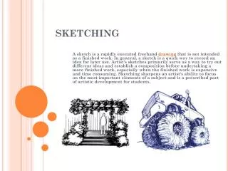
SKETCHING
SKETCHING. ALPHABET OF LINES. Object Line: Thick lines about .6mm(.032in) that show the visible edges of an object. Alphabet of Lines. Alphabet of Lines (cont.). Construction Line: Very lightly drawn line used as guide to help draw all other lines and shapes

SKETCHING
E N D
Presentation Transcript
SKETCHING ALPHABET OF LINES
Object Line: Thick lines about .6mm(.032in) that show the visible edges of an object. Alphabet of Lines
Alphabet of Lines (cont.) Construction Line: Very lightly drawn line used as guide to help draw all other lines and shapes properly. Usually erased after being used.
Object Line: Thick lines about .6mm(.032in) that show the visible edges of an object. Alphabet of Lines (cont.) Short Break Line: Freehand drawn line. Shows where a part is broken to reveal detail behind the part, or to shorten a long continuous part.
Alphabet of Lines (cont.) Section Lines: parallel “hatch” lines used to define where there is material after a part of the object is cut away.
Alphabetof Lines (cont.) Hidden Line: Used to show interior detail that is not visible from the outside of the part.
Alphabet of Lines (cont.) Center Line: Defines the center of arcs, circles, or symmetrical parts. Half as thick as an object line.
Drawing Views • For clear and accurate dimensioning and specification of a part the drawing may need a variety of views. • The basic views are: • Isometric • Oblique • Perspective • Orthographic • Section • Auxiliary • Assembly http://www.estfoundations.com/background3-basic%20project%20skills-sketching.html engin.brown.edu
Pictorial sketches • Pictorial sketches are sketches that show height, width, and depth all in one view. There are three common types: • Isometric • Oblique • Perspective http://ppdl.engr.ou.edu/ame2303/Draft.htm http://www.me.utexas.edu/~rbarr/sketching/perspective.html http://www.me.utexas.edu/~rbarr/sketching/oblique.html
Isometric Views • Isometric, meaning equal measure, created by rotating object at equal angles to the projection plane in order to appear inclined and to show three faces. • Corner is on horizon line • Isometric view often inserted in orthographic drawing. http://www.me.umn.edu/courses/me2011/handouts/drawing/blanco-tutorial.html#isodrawing
Width and depth lines are drawn at 30 degrees from the horizon line. Isometric sketch Note that one pictorial view shows height, width and depth.
Isometric View Isometric View
Oblique Oblique is easiest of sketches to draw Depth lines are drawn at an angle with the horizon.
Oblique Cavalier Front view is true size and shape. Oblique Cavalier looks distorted, but depth is true to size.
Oblique Cavalier (cont.) Width lines are parallel with the horizon. This cube has the same height, width and depth dimensions
Width lines are parallel with the horizon. In Cabinet Oblique, depth is half of true size. This allows the view to look more realistic. Front view is on hor- izon line, and is true size and shape. Oblique Cabinet
Perspective Views • Way to draw that shows view of object in most realistic way • Vanishing points used to guide lines in object to horizon line • We will discuss one and two point perspectives http://www.ider.herts.ac.uk/school/courseware/graphics/one_point_perspective.html
One Point Perspective All lines in depth project to one point (vanishing point). Location of vanishing point is based on line of sight.
Two Point Perspective In two point perspective, depth lines converge on one vanishing point (VP2) and width lines converge on other vanishing point (VP1).
Orthographic (Multiview Drawings) The arrows represent the line of sight associated with each view.
Orthographic Principal Views Note how the views are oriented. Each view is adjacent to the other as if they were unfolded from a 3D shape. Front, Top and Right views are used most often. You can see how other views resemble these three except they are not as clear due to hidden lines.
Section Views • To see the interior of parts, some of part is cut away. This allows for details to be seen clearly, gives alternative locations to properly dimension the part. Cutting plane line –short, short, long with arrows pointing to piece cut and turned so interior is visible http://en.wikipedia.org/wiki/Engineering_drawing
Full Section (cont.) A full section view shows what the object looks like if it were cut in half.
Full Section (cont.) A cutting plane line indicates how front view was cut. Labeled (A) in case another section is necessary. Arrows should point in line of sight as you are looking straight on at the section.
Full Section (cont.) Section lines called hatch lines are used to show where the part is solid. This helps to see the detail that would be normally blocked and only shown as hidden lines.
Auxiliary View • Projection plane parallel to a slanted surface to show as true shape and size. 90 degrees from that inclined face. Referred to as anAuxiliary View. Allows us to view surface in its true size and shape. www.engr.iupui.edu/~acheson/cgt110/ppt.../cgt110-week5.ppt
Primary Auxiliary View In order to see a feature in its true size and shape, we must look at it straight on or perpendicular to the plane in which the feature exists. Note that in this view (the auxiliary view) the slotted hole is true size and shape.
To obtain this view the auxiliary must be drawn from the view that allows the line of sight to be perpendicular to the desired feature. Line of sight. Primary Auxiliary View (cont.)
Detail Views • Drawing of individual part that contains all information needed to manufacture the object is referred to as Detail Drawing. Contain all the specifications, dimensions and views needed for production. • A Detail View may be necessary to illustrate small features on a part. Achieved via breaking out and enlarging the feature.
The feature is broken out and enlarged for clarity. Detail View
Assembly Drawings • General • Exploded • Explosion factor • Trails • Tweaks
General Assembly Drawings • General Assembly Drawings --set of drawings that include the detail drawings, assembly drawings and parts list needed in the production of an assembled object. ptc.com
Exploded Assemblies An Exploded Assembly shows all the parts removed from each other and aligned along axis lines