Download

1 / 36
360 likes | 383 Vues
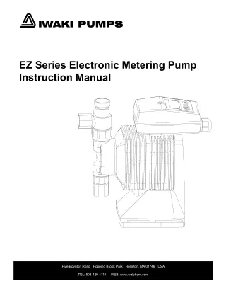
Access the comprehensive Iwaki America LK Series manual PDF to gain a deeper understanding of these high-quality metering pumps. This detailed manual provides step-by-step instructions for installation, operation, and maintenance of the LK Series pumps. Download the Iwaki America LK Series manual now to unlock the full potential of these versatile metering pumps for your industrial applications.

E N D
IWAKI AMERICA LK SERIES METERING PUMP INSTRUCTION MANUAL
Notice © 2013 Iwaki America Inc Five Boynton Road, Holliston, MA 01746 USA tel (508) 429-1440 fax (508) 429-1386 All Rights Reserved Printed in USA Proprietary Material The information and descriptions contained herein are the property of Iwaki America Inc. Such information and descriptions may not be copied or reproduced by any means, or disseminated or distributed without the express prior written permission of Iwaki America Inc. This document is for information purposes only and is subject to change without notice. Statement of Limited Warranty Iwaki America warrants equipment of its manufacture and bearing its identification to be free from defects in workmanship and material for a period of one year from date of delivery from the factory or authorized distributor under normal use and service and otherwise when such equipment is used in accordance with instructions furnished by Iwaki America and for the purposes disclosed in writing at the time purchased, if any. Iwaki America's liability under this warranty shall be limited to replacement or repair, F.O.B. Holliston, MA U.S.A. of any defective equipment or part which, having been returned to Iwaki America, transportation charges prepaid, has been inspected and determined by Iwaki America to be defective. THIS WARRANTY IS IN LIEU OF ANY OTHER WARRANTY, EITHER EXPRESS OR IMPLIED, AS TO DESCRIPTION, QUALITY, MERCHANT- ABILITY, FITNESS FOR ANY PARTICULAR PURPOSE OR USE, OR ANY OTHER MATTER. P/N 180312.L May 2013
TABLE OF CONTENTS Thank you for choosing an Iwaki America LK Series Metering Pump. This instruction manual deals with the correct installation, operation, maintenance and troubleshooting procedures for the LK metering pumps. Please read through it carefully to ensure the optimum performance, safety and service of your pump. IMPORTANT INSTRUCTIONS .................................................................................. 1 1 Operating Principle ........................................................................................... 3 2 Model Identification Guide ............................................................................... 4 3 Specifications and Outer Dimensions ............................................................ 4 4 Names of Parts .................................................................................................. 7 5 Description on Main Unit and Label .............................................................. 16 6 Handling Instructions ..................................................................................... 17 7 Installation ....................................................................................................... 18 8 Piping ............................................................................................................... 19 9 Wiring .............................................................................................................. 21 10 Operating Instructions ................................................................................... 21 11 Troubleshooting .............................................................................................. 26 12 Maintenance and Inspection .......................................................................... 27 13 Spare Parts ...................................................................................................... 29 14 Disassembly and Assembly ........................................................................... 29
IMPORTANT INSTRUCTIONS Important notes and statements about the safe operation and prevention of physical injury and/or property damage are included throughout this instruction manual. Always Observe These Safety Instructions! Safety Instructions to Prevent Personal Injury In this manual, the following symbols and signs are used to clearly indicate safety instructions: Warning Non-observance or misapplication of the contents of the "Warning" section could lead to a serious accident, including death or injury. Caution Non-observance or misapplication of the contents of the "Caution" section could lead to serious physical injury to the user or serious damage to the product. Caution (Always read and observe the following instructions to prevent personal injury.) Wear gloves when working with rope or chain. Working with bare hands may result in serious injury, since fingers are likely to be caught between the pump and the rope or chain when the rope or chain is under tension. The pump is not designed to be used under water. Install the pump in a clean, dry environment where the pump cannot become submerged. It is recommended that the pump be shielded from direct exposure to the elements. Install a safety valve on the discharge line. Installation of a pressure relief valve is highly recommended. Check local codes and regulations. Do not close off the discharge or suction lines while the pump is operating. The pump or piping may become damaged.
Warning (Always read and observe the following instructions to prevent personal injury.) Damaged or deteriorated tools are very dangerous.Use only qualified and suitable tools. Use protective gear.When disassembling, assembling, and conducting maintenance or when handling a dangerous type of liquid or a liquid of unknown property, be sure to wear safety gloves, a helmet, and protective shoes. In addition, when handling wet-end parts, always wear protective goggles, masks, etc. Prevent death or injury from a falling pump. Make sure the rope or chain used for lifting the pump is not accidentally cut or disconnected during installation. Make sure the rope or the chain used to lift the pump has sufficient strength for the pump load. Do not to stand underneath a lifted or suspended pump. Always turn off the power supply prior to servicing the pump.Make special provisions so that the power supply cannot be turned on while someone is working on the pump. In a noisy or poor visibility environment, display a sign near the power supply switch to notify others that someone is "WORKING" on the pump. Power mistakenly applied during maintenance may lead to personal injury. Check and make sure that there is no one near the pump when switching on the power supply. The pump is not equipped with an ON/OFF switch. Connecting the power cable or power plug supplies the power to the pump and starts the operation. Run the pump at the specified power supply voltage on the nameplate only. Fire or electric shock may result if the supply voltage is incorrect. If pump operation is stopped due to a power failure or closure of discharge line,turn off the power switch at once. After normal conditions are established, reapply power. Do not use the pump for anything that it is not designed to do.User’s failure to observe this instruction exempts Iwaki America from any responsibility for personal injury or damage to the equipment or facility caused by the pump’s misuse. When handling liquid with toxic or strong vapors,ventilate the working area well. In addition, the operator must wear protective gear (such as a safety mask, safety goggles, and protective gloves). Do not allow toxic substances such as lubricants, solvents, or similar substances to flow into the local sewage system or river systems. Do not drain hazardous liquids such as chemical solutions discharged out of the pump directly onto the ground. Instead, drain such liquids into an appropriate container. Observe the laws and regulations related to the application, handling, and processing of hazardous substances.
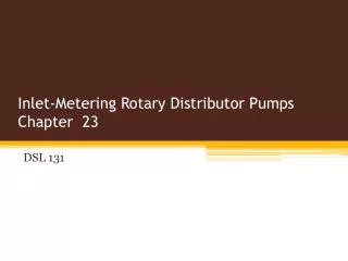
1 Operating Principle The rotation of the motor is reduced by means of the worm and wheel. The rotary motion is converted to a reciprocating motion by the spring-back mechanism (including the worm wheel shaft, slider, spring, etc.). The reciprocating motion is transmitted to the diaphragm directly connected with the shaft, changing the volume inside the pump chamber. The variation in volume inside the pump chamber and the functioning of the valves in the pump head produce the pump operation. To adjust stroke length, the adjusting dial fixed on the control shaft is rotated to change the return of the slider. WORM WHEEL SHAFT MOTOR DIAPHRAGM SLIDER DIAL SHAFT CONTROL SHAFT SPRING
2 Model Identification Guide LK N 32 A – VC 1 2 3 4 5 1 2 3 4 LK Series motor-driven metering pump N – NEMA 42C motor mounting flange Capacity/Pressure Rating. Refer to specifications and outer dimensions below. Motor Code: A = 115/230V, 60Hz, 1 ph, 1/3 HP, 1725 RPM, TEFC Frame 42C B = 230/460V, 60Hz, 3 ph, 1/3 HP, 1725 RPM, TEFC Frame 42C C = 190/380V//230/460V, 50/60Hz, 3 ph, 1/3 HP, 1450/1725 RPM, TEFC, Frame 42C D = 90VDC, 1 ph, 1/3 HP, 1750 RPM, TENV, Frame 42C Variable Speed Motor, 115V Control E = 180VDC, 1 ph, 1/3 HP, 1750 RPM, TENV, Frame 42C Variable Speed Motor, 230V Control F = 230/460V, 60Hz, 3 ph, 1/3 HP, 1725 RPM, Explosion Proof Motor: Class 1, Div 1, Group C & D G = 230/460, 60 Hz, 3 ph, 1725 RPM, Inverter Duty Motor, TENV, 42C 5 Liquid End Code. Refer to the table below. Material symbol Pump head Valve ball VC PVC CE FKM PVC FKM VH PVC HC EPDM PVC EPDM VS PVC TC PVDF CE FKM PVDF FKM S6 316 SS HC 316 SS 316 SS - HC/304 SS 304 SS 304 SS EPDM PTFE PTFE + EPDM Type 32 Type 45 to 57 Valve seat Part O ring Valve gasket Diaphragm CE: Alumina ceramic Specifications and Outer Dimensions HC: Hastelloy C267 3 Maximum Pressure PSI (MPa) Stroke speed (spm) Connection NPT Capacity Viscosity cps Model 50Hz (l/h) 30 50 100 168 360 60Hz (GPH) 9.5 15.9 31.8 53.4 114.3 PVC/PVDF SS 50Hz 60Hz PVC/PVDF SS LKN32 LKN45 LKN47 LKN55 LKN57 150 (1) 150 (1) 120 (0.8) 75 (0.5) 45 (0.3) 225 (1.5) 225 (1.5) 120 (0.8) 75 (0.5) 45 (0.3) 96 48 96 48 96 116 58 116 58 116 * LKN47-VS has 1” NPT connections ½” ½” ½” * 1” 1” ½” ½” ½” 1” 1” VC: 300 TC: 300 VH: 500 VS: 1000 S6: 1000
Outer dimensions LKN32, 45, 47, 55, 57, VC, VH, VS Dimensions in inches (mm) Model F 6.50" (165mm) A 2.00" (51mm) K E 3.35” (85mm) 0.79” (20mm) j 3.94" (100mm) c 4.72" (120mm) 4.92” (125mm) L L A C E F J K 10.88 (276) 12.125 (308) 3.88 (99) 4.063 (103) 4.688 (119) LKN32, VC, VH, VS ½” NPT 10.94 (278) 12.00 (305) 3.94 (100) 4.00 (102) 4.75 (121) LKN45, 47, VC, VH, VS 4 x ø0.35” (ø9) 10.94 (278) 10.125 (257) 3.94 (100) 3.06 (78) 4.75 (121) LKN47VS 1” NPT 12.375 (314) 12.25 (311) 4.50 (114) 4.125 (105) 5.313 (135) LKN55, 57, VC, VH, VS
Outer Dimensions LKN32, 45, 47, 55, 57, S6 F 6.50" (165mm) A 2.00" (51mm) E K 3.94" (100mm) 4.72" (120mm) 3.35" (85mm) Dimensions in inches (mm) j 4.92" (125mm) L Model L A C E F J K 10.88 (276) 7.95 (202) 3.88 (99) 1.88 (48) 4.688 (119) LKN32, S6 ½” NPT 11.00 (279) 12.00 (305) 4.00 (102) 4.00 (102) 4.81 (122) LKN45, 47, S6 4 x ø0.35” (ø9) 12.125 (308) 15.25 (387) 4.25 (108) 5.625 (143) 5.188 (132) LKN55, 57, S6 1” NPT
Outer Dimensions LKN32, 45, 47, 55, 57, TC F 6.50" (165mm) 2.00" (51mm) A E 3.94" (100mm) 3.35" (85mm) 0.79" (20mm) c 4.72" (120mm) 4.92" (125mm) L Dimensions in inches (mm) Model L A C E F J K 10.88 (276) 12.125 (308) 3.88 (99) 4.06 (103) 4.688 (119) LKN32, TC ½” NPT 10.44 (265) 13.50 (343) 3.44 (87) 4.75 (121) 4.75 (121) 4 x ø0.35” (ø9) LKN45, 47, TC 12.375 (314) 12.25 (311) 4.50 (114) 4.188 (106) 4.125 (105) LKN55, 57, TC 1” NPT
4 Exploded View and Parts List LKN32 VC, VH, VS 6* 6 VC VH VS No. Part Qty Part No. L0770 Material PVC Alumina Ceramic PVC FKM PTFE PVC FKM FKM Part No. L0770 Material PVC Part No. L1227 Material PVC 1 Pump head 1 *2 Ball 2 L0063 L0062 Hastelloy C L0062 Hastelloy C *3 *4 *5 6 *7 *8 Valve guide Valve seat Valve Gasket Adapter O-ring O-ring 2 2 2 2 2 2 L0064 L0066 L0068 L0072 L0074 L0016 L0064 L0065 L0068 L0072 L0073 L0015 PVC EPDM PTFE PVC EPDM EPDM L0488 L0489 L0068 L0072 L0073 L0015 PVC SS304 PTFE PVC EPDM EPDM L0506 (PVC) is used on the suction side. No. Part Qty Part No. Material Hex head bolt Split washer Plate washer Reinforcing plate Diaphragm Retainer Nut Fitting * Parts included in the spare parts kit. 20 21 22 29 *30 *31 50 51 6 6 6 1 1 1 2 2 L0246 EH2010 EH2011 L0771 L0080 L0081 L0022 L1590 SS SS SS Steel PTFE + EPDM SS304 PVC PVC
LKN45, 47 VC, VH, VS 50 22 50 VC VH VS No. Part Qty Part No. L1500 Material PVC Alumina Ceramic PVC PVC PTFE FKM Part No. L1500 Material PVC Part No. L1500 Material PVC 1 Pump head 1 *2 Ball 2 L0093 L0092 Hastelloy C L0092 Hastelloy C *3 *4 *5 *7 Valve guide Valve seat Valve Gasket O-ring 2 2 2 2 L0094 L0095 L0097 L0103 L0094 L0095 L0097 L0102 PVC PVC PTFE EPDM L0094 L0096 L0097 L0102 PVC SS304 PTFE EPDM No. Part Qty Part No. Material Notes 20 22 29 *30 *31 50 51 51 * Parts included in the spare parts kit. Hex head bolt Plate washer Reinforcing plate Diaphragm Retainer Nut Fitting, ½” NPT Fitting, 1” NPT 8 8 1 1 1 2 2 2 L1166 L1610 L1224 L0109 L0110 L1596 L1593 L1595 SS SS FC200 PTFE + EPDM SS304 PVC PVC PVC For LKN45/47-VC/VH and LKN45-VS For LKN47-Vs only
LKN55, 57 VC, VH, VS 50 22 50 VC VH VS No. Part Qty Part No. L1513 Material PVC Alumina Ceramic PVC PVC PTFE FKM Part No. L1513 Material PVC Part No. L1513 Material PVC 1 Pump head 1 *2 Ball 2 L0151 L0150 Hastelloy C L0150 Hastelloy C *3 *4 *5 *7 Valve guide Valve seat Valve Gasket O-ring 2 2 2 2 L0152 L0153 L0155 L0161 L0152 L0153 L0155 L0160 PVC PVC PTFE EPDM L0152 L0154 L0155 L0160 PVC SS304 PTFE EPDM No. Part Qty Part No. Material 20 22 29 *30 *31 50 51 * Parts included in the spare parts kit. Hex head bolt Plate washer Reinforcing plate Diaphragm Retainer Nut Fitting 8 8 1 1 1 2 2 L1168 L1610 L1600 L0167 L0168 L1596 L1595 SS SS FC200 PTFE + EPDM SS304 PVC PVC
LKN32 S6 No. Part Qty Part No. Material 1 *2 *3 *4 *5 *6 20 21 22 *30 *31 70 Pump head Ball Valve guide Valve seat Valve gasket A Valve gasket B Hex head bolt Split washer Plate washer Diaphragm Retainer plate Fitting 1 2 2 2 4 2 6 6 6 1 1 2 L1204 L0062 L1205 L1206 L0244 L0245 L0246 EH2010 EH2011 L0080 L0081 L1592 SS316 Hastelloy C SS316 SS316 PTFE PTFE SS SS SS PTFE + EPDM SS304 SS316 * Parts included in the spare parts kit.
LKN45, 47, 55, 57 S6 71 22 71 Part No. for LKN45, 47 L1209 L0092 L0826 L0827 L0257 L1167 L1610 L0109 L0110 L1594 L1509 L0762 L1512 Part No. for LKN55, 57 L1212 L0265 L1213 L1214 L0269 L1167 L1610 L0167 L0168 L1599 L1518 L1523 L0189 No. Part Qty Material 1 *2 *3 *4 *5 20 22 *30 *31 71 80 81 82 Pump head Ball Valve guide Valve seat Valve Gasket Bolt w/split washer Plate washer Diaphragm Retainer plate Fitting Stud bolt Hex nut Split washer 1 2 2 2 6 8 8 1 1 2 8 8 8 SS316 Hastelloy C SS316 SS316 PTFE SS SS PTFE + EPDM SS304 SS316 SS SS SS * Parts included in the spare parts kit.
LKN32 TC No. Part Qty Part No. Material 1 *2 *3 *4 *5 *6 *7 *8 20 21 22 29 *30 *31 50 51 Pump head Ball Valve guide Valve seat Valve Gasket Adapter O-ring O-ring Bolt Split washer Plate washer Reinforcing plate Diaphragm Retainer plate Nut Fitting 1 2 2 2 2 2 2 2 6 6 6 1 1 1 2 2 L1226 L0063 L0332 L0066 L0068 L0335 L0074 L0016 L0246 EH2010 EH2011 L0771 L0080 L0081 L1611 L1591 PVDF Ceramic PVDF PVDF PTFE PVDF FKM FKM SS SS SS SS41 PTFE + EPDM SS304 PVDF PVDF * Parts included in the spare parts kit.
LKN45, 47 TC No. Part Qty Part No. Material Pump head Ball Valve guide Valve seat Valve Gasket Adapter O-ring O-ring Nut Bolt w/split washer Plate washer Reinforcing plate Diaphragm Retainer plate Nut Fitting * Parts included in the spare parts kit. 1 *2 *3 *4 *5 6 *7 *8 9 20 22 29 *30 *31 50 51 1 2 2 2 2 2 2 2 2 8 8 1 1 1 2 2 L1505 L0093 L0347 L0348 L0097 L0350 L0103 L0016 L1539 L1166 L1610 L1224 L0109 L0110 L1611 L1591 PVDF Ceramic PVDF PVDF PTFE PVDF FKM FKM PVDF SS304 SS SS41 PTFE + EPDM SS304 PVDF PVDF
LKN55, 57 TC No. Part Qty Part No. Material Pump head Ball Valve guide Valve seat Valve Gasket O-ring Bolt w/split washer Plate washer Reinforcing plate Diaphragm Retainer plate Nut Fitting * Parts included in the spare parts kit. 1 *2 *3 *4 *5 *7 20 22 29 *30 *31 50 51 1 2 2 2 2 2 8 8 1 1 1 2 2 L1521 L0151 L0363 L0364 L0155 L0161 L1168 L1610 L1600 L0167 L0168 L1598 L1597 PVDF Ceramic PVDF PVDF PTFE FKM SS304 SS FC200 PTFE + EPDM SS304 PVDF PVDF
5 Description on Main Unit and Label Motor Reducing mechanism Discharge Stroke Length Knob/Indicator The stroke length can be adjusted through a range of 100% to 0% by rotating the dial. Specification Nameplate Model number and specifications are indicated on the nameplate. Operate the pump within the limits of the specifications. Pump (Liquid end) Suction Port Caution: Do not use any solvent when wiping the nameplate, labels or the pump main unit.
6 Handling Instructions Warning Do not operate the pump with dangerous or hazardous mediums (such as explosive, combustible, flammable, or toxic substances). Caution Read the following information prior to installation of the pump: Protective gear: When operating the pump or working near it, always wear protective clothing, face guard, goggles, and gloves. Further precautionary measures must be taken depending upon the type of liquid used. Pump repair: Do not try to disassemble or repair the pump beyond the range specified in this instruction manual Contact the local distributor for further help. 1. Handle the pump carefully. Impacts caused by dropping the pump on the floor or striking it may result in damage or faulty performance. 2. Do not operate the pump under the following condition: where the temperature falls below 0°C where corrosive gas or explosive gas may be present exposed to splashing water where the ambient temperature is 40°C or above where the humidity is excessively high (Permissible humidity: 35~85%RH) places filled with or likely to be filled with explosive or corrosive atmosphere danger due to dust, fire, earthquake and/or any externally imposed shock 3. Keep the pump away from fire. To prevent fire and explosions, do not place dangerous or flammable substances near the pump. 4.Damaged pump or motor Do not operate a damaged pump due to the possibility of electric shock. 5. Pump modification Never attempt to modify the pump. This may cause a serious accident or damage. 6. No disassembly or repair Users should not disassemble and repair the pump beyond the level given in the "Disassembly and Assembly" section of this manual. Caution The pump must be repaired by trained and qualified operators only. If in need of repair, stop operation and contact your supplier for service.
7. Do not close the discharge or suction lines while in operation. Pump operation with valves closed increases the load onto the pump itself and will eventually damage the pump or piping. 8. Do not adjust the stroke length while the pump is not operating. Rotating the stroke adjustment dial while not in operation applies load onto the dial and will eventually damage the pump. 9. Allowable pressure limit Set the discharge pressure at or below the allowable pressure limit level indicated in the “Specifications” section. 10. Temperature/humidity fluctuation Temperature fluctuation may not affect the performance of the pump itself. However, the liquid may change in terms of its viscosity, pressure, or corrosion resistance. Pay special attention to changes in liquid characteristics as a result of temperature fluctuation. Liquid temperature range: Material symbol VC, VH, VS: Material symbol S6, TC: Ambient temperature range: Humidity range: 0~50°C 0~80°C 0~40°C 35~85%RH 7 Installation 1. Installation position Install the pump as close to the suction tank and as low as possible. Flooded suction is the ideal installation. The suction lift ability depends upon the liquid properties, temperature, and length of the suction piping. For details of the setup, consult your distributor. Indoor and outdoor use The pump can be operated either indoors or outdoors. However, safety measures should be taken so as not to expose the motor and power distribution unit to flooding and it is always, recommended that the pump be shielded from direct exposure to the elements (snow, direct sun, etc.). Installation site Select an installation site that is flat and free of vibrations caused by nearby machines. Sufficient space for maintenance should be provided. 2. 3. Lifting Lift the pump horizontally so that the gear oil will not leak out of the pump drive unit.
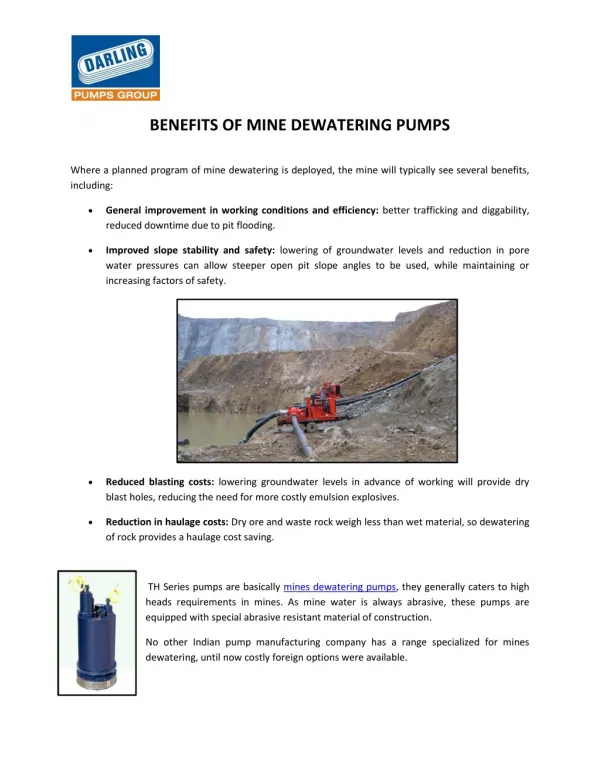
Foundation preparation (before pump installation) 1.The area for anchoring the pump should be greater than the area of the pump base. If the anchoring area is too small, the base may be destroyed due to the concentrated load on it. 2.If pump operation is to be subject to vibration (resonation with the piping, for example), provide an expansion joint between the pump and the piping. Otherwise, the piping, gauge, etc., may be damaged. 3. Installation advice • Use anchor bolts to fasten the pump base firmly. • Install the pump horizontally. • Sufficient space is required to allow cool air from the motor fan to circulate. • Allow ample space around the pump for easy and efficient maintenance work. 8 Piping Back Pressure Valve Pressure Relief Safety Valve Discharge Valve Pulsation Dampener or Air Chamber Shut off Valve PG Expansion joint Air Vent Valve (flushing valve) P Suction Valve Expansion joint Drain Valve (flushing valve) Load of piping for LK-N When plumbing the pump, support the piping and use an expansion joint so as not to apply a load onto the pump discharge/suction ports. General precautions 1.All piping should be supported independently so that unnecessary weight and vibration are not transmitted directly to the pump. Expansion joint is recommended to avoid damaging the pump head especially.
2. The best piping arrangement for minimum pressure loss is achieved with straight runs and full bore piping containing as few bends and fittings as possible. 3. When handling a high or low temperature liquid, provide an expansion joint in the pipeline to allow for stress caused by thermal expansion and contraction. 4. When handling a slurry liquid, provide a drain plug at the bottom of the piping and do not make a “trap” in the piping system. 5.When handling a viscous, toxic or a liquid that easily crystallizes, install piping for cleaning. 6.Use adequate piping materials that can resist pressure and corrosion. 7.Clean the inside of pipes before installation. Remove the caps fitted on the pump inlet and outlet before installing piping. The caps are provided for preventing contamination by foreign matter. 8.A pressure relief safety valve and a pulsation dampener should be installed on the discharge line near the pump. CAUTION! Operation without a pressure relief safety valve installed could result in catastrophic failure and a dangerous condition if the discharge line is closed for any reason during operation Suction piping 1.Flooded suction is always recommended. 2.The diameter of the suction pipe should never be smaller than the size of the pump inlet. 3.The suction piping should be as short as possible. Excessive length may lead to flow restriction, cavitation and damage to the pump. 4.Air ingress from the joints in the piping system may cause pumping damage or inconsistent flow. Make sure the joints are well sealed. Discharge piping 1. Install a pressure relief safety valve as close to the pump discharge as possible. Its setting pressure should not exceed the pressure permissible for the pump and pipes. Maintain pipe diameter (match pump discharge size) through discharge point including all valves and injectors. At a minimum, match size through pressure relief valve to ensure safety and protect the pump. 2. 3. Firmly connect and seal all the joints using proper pipe support (this includes flexible tubing as pulsation and tubing flex can stress pump head connection). 4. Install a pressure gauge on the discharge piping to verify actual pressure in discharge. The pressure gauge must be installed before any pipe reductions to measure an accurate pressure to the pump.
5. Install a pulsation dampener (air chamber or accumulator) in the discharge piping to prevent any fluctuation of pressure. Install the pulsation dampener in a position close to the pump discharge port. A pulsation dampener will significantly increase the life of the pump. 9 Wiring Electrical connections WARNING The electrical connection should be carried out by an authorized electrician in accordance with local regulations. Please make sure that the electrical data on the nameplate of the motor corresponds to the electrical supply on which it will be used. Motors must be connected to a motor protection switch. 1.Use an electromagnetic switch that conforms to the specifications (voltage, capacity, etc.) of the pump motor. 2.If using the pump outdoors, waterproof the wiring to protect the switches from rainwater. 3.Electromagnetic switches and push buttons should be installed at a reasonable distance from the pump. 10Operating Instructions 1.Never operate the pump with the suction and discharge side valve closed. Otherwise, the inside of the pump or the piping will be damaged. 2.In the event of a service power failure, turn off the power switch immediately and close the discharge valve. 3. Maximum pump surface temperature (not motor) The max. pump surface temperature of each model is shown in the table. Arrange protective measures in accordance with the temperature levels. Liquid temp °C 50 80 Max. surface temp. at 40°C ambient temp °C 45 75 Model LKN32, 45,47,55,57 VC, VH, VS LKN32, 45,47,55,57, S6 4. Sound generated by pump
The level of sound generated by LKN type of pump is 85 (dB). Arrange a muffling device to reduce the sound level if necessary. The procedure for sound measurement conforms to the EN 31201 (ISO11201).
Preparation for start-up The following inspections should be made before the initial operation after installation and operation after a long period of inactivity. 1. Thoroughly clean the inside of the tank and pipe. Then, supply liquid. 2. Tighten the pump connections and the installation bolts on the base. 3. Check every part of the pump for defects, loosened bolts, oil leakage, etc. 4Check the oil gauge to see if the drive unit is filled with the specified amount of oil. Oil Cap Oil Gauge 5.Run the motor instantaneously to check for correct direction of motor rotation. The motor should run in the direction indicated with the arrow on the pump. If the direction is reversed, rewire the motor power wires in accordance with the wiring schematic on the motor nameplate. Operation 1. Open the valves of the suction and discharge pipes. Caution DO NOT OPERATE THE PUMP WITH THE VALVES CLOSED. 2.Provide power to the motor. 3. Loosen the hex socket head bolt of the stroke length dial. Set the stroke length to 0% by turning the stroke length dial clockwise Caution DO NOT TURN THE DIAL WHILE THE PUMP IS NOT OPERATING. Hex socket head bolt Stroke length dial
4. Continue to run the pump for 30 minutes or longer to let it warm up. Check that no abnormality is found. This procedure is necessary only during the first operation, but when the ambient temperature is extremely low, continue no-load running until the oil temperature rises sufficiently because the motor may sometimes be overloaded a little due to an increase in the viscosity of oil in the drive unit. 5. Open an air vent valve to purge the discharge line of air. 6.Increase the stroke length up to 100% and continue to run the pump for 30 minutes or longer again. 7.Close the air vent valve gradually, watching the pressure gauge. The liquid will come into the discharge line and be discharged from the end of the pipe. Should the discharge pressure exceed the permissible pressure for the pump before the air vent valve is completely closed, check the piping system. 8.Check that the motor amperage does not exceed the rated value and that no abnormality is found. Metering and Calibration 1. Operate the pump using the actual liquid and installation conditions. 2. Setting the stroke length at 100%, determine the discharge capacity per minute several times. If no noticeable variation is found after repeated measuring, the pump is working normally. 3. Measure the discharge capacity at two or three points of the stroke length. When a set point is changed, measure the discharge capacity after running one minute or longer. 4. Plot a pump calibration curve using the results of the above procedures. [Note] Our in-plant test data is based on pumping water at normal ambient temperature with a short piping system. Therefore, there will be a difference between the test data and the practical performance data. 5. The relationship between the amount of stroke length dial revolution and stroke length is shown in the following graphs. LKN3 LKN4 LKN5 20 40 60 80 100 25 50 75 100 25 50 75 100 Stroke length Stroke length Stroke length 0 2 4 6 8 10 Revolution 0 1 ½ 3 4½ 6 Revolution 0 ½ 1 1½ 2 Revolution
Starting after the pump is stopped or out of use 1. When the pump is stopped for a short period of time (within a week), it can be re-started at its prescribed pressure and capacity. 2. When the pump has been out of use for a long period of time, operate the pump at zero pressure for a few minutes to lubricate it thoroughly. Do not start the pump at a prescribed pressure immediately. Pulsation dampener It is always recommended to install a pulsation dampener, i.e. diaphragm type accumulator, air chamber, etc. Because a metering pump is a reciprocating device, it produces pressure pulsations that the system sees in the form of acceleration, inertia, shock, noise, and reduced service life. When the piping is long, it is especially important to use a pulsation dampener for accurate metering.
11 Troubleshooting Ref. No. for Item Problem Cause/Countermeasure 1, 2, 4, 5, 6, 7, 8, 9, 11, 12 3, 7, 9 1, 2, 3, 4, 5, 7, 8, 11, 12 1, 2, 4, 7, 8, 11, 12 1, 2, 4, 8, 10, 11, 12 1, 2, 4, 5, 6, 7, 8, 12 5, 6 15, 16, 17, 18, 19 13, 15, 16, 17, 19 8, 12, 13, 15, 19 14 7, 13, 19 Discharge capacity is low. Discharge capacity is excessive. Discharge capacity is unstable. No liquid is discharged. Discharge pressure does not increase. Pump will not prime. Liquid leaks. Motor does not run. Motor draws excessive amperage. Excessive vibration and loud noise. Oil leaks. Gearbox temperature is excessive. A B C D E F G H I J K L Ref. 1 Cause Countermeasure Foreign matter is clogging valve ball, valve seat and/or valve guide. Valve seat and/or valve ball is worn. Differential pressure is inadequate. Disassemble and clean. Replace. Install a back-pressure valve in discharge line. (5 PSI is required as min. differential pressure.) Inspect suction pipes and connections. Re- tighten. Replace. Replace. Check the discharge pressure for foreign matter or crystallization in the pump chamber if it fails prematurely. Renew pump performance data of the altered pumping condition after confirming that the pump is good. Disassemble and clean. Readjust and tighten lock bolt securely after confirming that no liquid is discharged at stroke length of 0%. Clean or replace. 2 3 4 Air leaks into suction line. 5 6 Defective valve gasket or O-ring Damage to diaphragm 7 Pumping condition (liquid, temperature, pressure, piping, etc.) changes. 8 9 Suction pipe or strainer is clogged. Stroke length dial has moved. 10 Dust is clogging mouth of pressure gauge or pressure gauge is defective. Leak from safety valve 11 Readjust pressure setting or replace if it is defective. Examine suction conditions. Check that the correct oil has been used. Check the oil quantity and level. Replenish or replace if necessary. Replace. Replace. Check wiring. Replace switch, etc. if necessary. 12 Cavitation occurs due to insufficient NPSHr. 13 Lubricating oil of the drive unit is not correct. 14 15 16 Defective oil seal or O-ring Defective motor Wrong wiring or defective contact
Ref. Cause 17 Voltage drop Countermeasure Inspect cause and take countermeasures accordingly. Inspect cause and take countermeasures accordingly. Check discharge line and take countermeasures to lower the pressure. 18 Blown fuse. 19 Overload (excessive discharge pressure) 12 Maintenance and Inspection Daily inspection 1.Check whether the pump operates smoothly and without any abnormal noise or vibration. 2.Check the level of the liquid in the solution supply tank. 3.Check the pump and piping for leakages. 4.Check the drive unit for oil loss and leakage. 5.Compare the discharge pressure and electric current measured during operation with the values indicated on the motor nameplate for verification of normal pump load. Note that the values indicated on the pressure gauge vary in proportion to the specific gravity of the liquid. The valve to the pressure gauge must be opened only when measurement is carried out. It must be closed upon the completion of each measurement. If the valve remains open during pump operation, the meter mechanism in the gauge may be affected or damaged by noise or vibration. 6.If a spare pump is available, activate it from time to time to keep it ready for use any time. Check to be sure there are no leaks from the pump before operating it. If leakage is detected, never try to operate the pump. 7. Check to be sure the discharge pressure, discharge flow rate, and motor power supply voltage do not fluctuate during pump operation. If considerable fluctuation is observed, refer to the Troubleshooting section for corrective measures.
Periodic inspection To ensure efficient and smooth operation of the pump, periodically inspect the pump and installation. When inspecting, overhauling, or if repair is necessary, stop the pump operation and contact the supplier as necessary. The overhauling and repair work for Iwaki America pumps must be performed by qualified personnel who have been trained and certified by the pump supplier. User’s failure to observe this instruction exempts Iwaki America from the responsibility for personal injury or damage to the equipment or facility that result from its misuse. 1. Valve Unit Check the valve balls, valve seats and valve guides every 6 months. If flaws or worn parts are found, replace them. 2. Diaphragm Check the diaphragm every 6 months if the usage is fairly light. The life of the diaphragm depends on the characteristics, pressure, temperature, etc. of the liquid being pumped. If any deformation or crack is found, the diaphragm should be replaced with a new one. 3. Oil Change the oil in the drive unit once a year. If emulsification of the oil is found during inspection, immediately change the oil. Remove the drain plug and drain the drive unit. Flush the inside with oil to clean it. Then, add new oil up to the specified level of the oil gauge. Ensure any replacement oil is SAE (80W-90) and must exceed API Service GL-4. Model Oil Qty LKN 7.44oz (220 mL) Mobil Pegasus Gear Oil 80 (Automobile Gear Oil SAE-80, API Grade GL-4), Castrol Hypoy Gear Oil Contact your Iwaki America distributor if the oil listed above is unavailable. Use of incorrect oil may shorten the life-term of the gear unit. Recommended Oil Esso (Exxon) GP80W-90, Shell Spirax/EP80, Drain plug
13Spare Parts If downtime is critical, it is recommended to always maintain a stand-by pump and a spare parts kit if the pump is being used continuously. Recommended Spare Parts Valve, Valve guide, Valve seat Estimated Service Life 12 months (life is dependent on the characteristics of liquid being pumped) 12 months (o-rings and gaskets shall be replaced at each disassembly) 4,000 hrs (life is dependent on the discharge pressure, liquid, temperature, etc.) 3 years O-ring and Gasket Diaphragm Drive unit Note: The above service life figures are only estimates and not a guarantee. Actual application will determine pump life. 14 Disassembly and Assembly Refer to exploded view of the model corresponding to your pump. The views are shown in Section 4 – Exploded View and Parts List. Caution • Before disassembling/assembling the pump, to turn off the main power supply. Display a “WORKING” sign near the power switch to let other personnel know the situation. Accidental power ON initiated by an other person may result in an accident. The operator must take special precautions to prevent this situation. • Prior to disassembly or assembly, close the suction valve and discharge valve fully. • The piping and the pump often retain liquid. When working around a dangerous liquid, wear appropriate protection (goggles, rubber gloves, etc.) when disconnecting the pipes and decontaminating the pump.
Disassembly 1. Disassemble only after thoroughly decontaminating the pump by flushing and cleaning the piping and the inside of the pump. Warning Wear protection (goggles, rubber gloves, etc.). Certain liquids are dangerous and may hurt your eyes and skin. 2. Remove the discharge and suction piping. Caution Close the suction valve and discharge valve fully, prior to removing the discharge and suction piping. Valve 1. Remove the suction and discharge fitting by loosening the nut (50). Remove the adapter (6) if any, and take out the valve (2), valve guide (3), valve seat (4), valve gasket (5) and O-ring (7). If the pump head is made of stainless steel, the valve assembly can be taken out by loosening the setting flange (54) or the nuts (81). 2. Check the valve and valve seat. If they are damaged or worn, replace with a new ones. It is highly recommended to replace the gasket and O-ring every time the liquid end is disassembled. Diaphragm 1.Loosen the hex head or socket head cap bolts (20). 2. Remove the pump head (1). 3. Connect power supply and run the motor temporarily (without the liquid end). Set stroke length to 100%. Turn off when the diaphragm comes to the top dead center (when the diaphragm is most extended). Disconnect power supply. Spanner Caution Do not touch any moving parts during operation. Hex head bolt (20) 4. Remove the diaphragm from the pump shaft by turning the diaphragm counterclockwise with hand. If it is worn or deformed part in any way, replace it with a new one
. 5. Attach the new diaphragm firmly to the pump shaft by turning it clockwise by hand (hand tighten only, no tools). Confirm that the retainer (31) is sitting correctly around the diaphragm insert bolt and rests against the end of the pump shaft. If the position of the pump shaft moves during reassembly of the diaphragm, set it at top dead center, following the above procedure #3. Diaphragm (30) Bracket Retainer (31) Pump shaft Diaphragm insert bolt Bottom dead center Stroke Length, 100% Top dead center Assembly The pump should be assembled by carrying out the steps of disassembly in reverse. Pay special attention to the following points: Valve 1. Replacement of o-ring and gasket Replace the o-ring or gasket, with a new one. Additionally, ensure that the o-ring or gasket is not twisted or pinched between parts. * The sealing section should be free of dust or scratches before installation. 2. Assemble the valve assembly by reversing the procedure, taking special care with the direction and position of the valve guide, valve seat and valve gasket. Caution If the direction or position of the valve guide, valve ball, or valve seat is incorrect, the pump will not pump and/or may be damaged.
3. When installing the LKN32 fiiting/nut (VC, VH, or VS type), use a spanner wrench to hold the adapter (6) then fasten the nut (50) by hand. Spanner Spanner Diaphragm 1. Connect power supply and temporarily run the motor, moving the diaphragm to the bottom dead center where the diaphragm is fully drawn back. Turn off motor. Caution Only attach the head when the diaphragm is at bottom dead center. Premature diaphragm failure may occur if this step is not observed. Do not touch any moving parts during operation. 2. Fit the pump head (1) to the bracket of the drive unit with the hex head or socket head cap bolts (20). Tighten all the bolts securely and uniformly. Tighening torque for bolts (20) LKN 32 VC, VH, VS, TC 27 in-lbs (3.0 Nm) 106 in-lbs (12.0 Nm) LKN 45, 47 LKN 55, 57 106 in-lbs (12.0 Nm) S6 44 in-lbs (5.0 Nm) 106 in-lbs (12.0 Nm) 106 in-lbs (12.0 Nm)
Five Boynton Road Hopping Brook Park Holliston, MA 01746 USA TEL 508-429-1440 FAX 508-429-1386 www.IwakiAmerica.com