Microchip for Drug Delivery
280 likes | 2.4k Vues
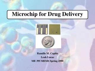
Microchip for Drug Delivery Ramille M. Capito Leah Lucas ME 395 MEMS Spring 2000 Presentation Outline Introduction: Why the use of a microchip? Microchip Design/Microfabrication Gold Dissolution Circuit Design Power Source Conclusions Drug Delivery

Microchip for Drug Delivery
E N D
Presentation Transcript
Microchip for Drug Delivery Ramille M. Capito Leah Lucas ME 395 MEMS Spring 2000
Presentation Outline • Introduction: Why the use of a microchip? • Microchip Design/Microfabrication • Gold Dissolution • Circuit Design • Power Source • Conclusions
Drug Delivery • Very important aspect of medical treatment. • Drug effectiveness directly related to the way in which drugs are administered --can make it very difficult to select the proper drug delivery system. • Some therapies require that the drug be repeatedly administered to the patient over a long period of time, or in specific amounts at a time in order to maximize drug effectiveness.
Problems with Current Methods of Drug Delivery • In many cases, patients often forget, are unwilling, or are unable to take their medication • Some drugs too potent for systemic drug delivery (intravenous) and may cause more harm than good • Great advantage: a drug delivery device that is capable of controlled, pulsatile or continuous release of a wide variety of drugs and other therapeutics that can be safely implanted inside the body
Other Drug Delivery Systems Attempting to Control Drug Release • Polymeric devices: Problem: too simple to have the ability to precisely control the amount or rate of drug released. • Electromechanically driven devices: Problem: miniature power-driven mechanical parts required to either retract, dispense, or pump in order to deliver drugs in the body complicated and are subject to breakdown (i.e. fatigue or fracture). --complexity and size restrictions unsuitable to deliver more than a few drugs or drug mixtures at a time.
What is Novel About this Microchip? • It is the first device of its kind enabling the storage of one or more compounds inside of the microchip in any form(solid, liquid, or gel), with the release of the compounds achieved on demand and with no moving parts.
Microchip Design • Each reservoir is capped with a conductive membrane (i.e. gold) and wired with the final circuitry controlled by a microprocessor. • simple to use and manufacture • biocompatible and small enough to be implantable in the human body • A strong, non-degradable, easily etched substrate that is impermeable to the delivered chemicals and non-degradable to the surrounding environment within the body is silicon. • The substrate contains multiple reservoirs capable of holding chemicals in the solid, liquid, or gel form. • delivery of drugs for weeks or years at a time • varying dosages—should release substances in a controlled dependable manner
Microfabrication Process 1.) Deposit layer of insulating material, silicon nitride (0.12 mm), onto the substrate by PECVD 2.) Pattern by photolithography and square reservoirs are etched by ECR-enhanced RIE 3.) With potassium hydroxide solution at 85C, anisotropically etch square pyramidal reservoirs into the silicon along the (111) crystal 4.) Invert and deposit gold electrodes (0.3-0.5 mm thick). Pattern by E-beam evaporation and liftoff.
5.) Deposit electrode protective coating, silicon dioxide, by PECVD. Silicon dioxide over anode, cathode and bonding pads are etched with ECR-enhanced RIE to expose gold film. 6.) Remove SiN layer in the inside of reservoir by RIE to expose gold membrane. 7.) Fill reservoirs by inkjet printing through opening (500 mm x 500 mm)
Reservoir Filling Substrate Vapor Bubble Heater Drug PV = nRT
Microfabrication Process (cont’d) 8.) Bottom of reservoirs capped with a silicon nitride coating 9.) Device can now be patterned with IC control circuitry and thin-film battery.
Why the Gold Membrane? is chosen as the model membrane material: • It is easily deposited and patterned • Gold has a low reactivity with other substances and resists spontaneous corrosion in many solutions over the entire pH range. • The presence of a small amount of chloride ion creates an electric potential region which favors the formation of soluble gold chloride complexes. • Holding the anode potential in this corrosion region enables reproducible gold dissolution. --Potentials below this region are too low to cause appreciable corrosion, whereas potentials above this region result in gas evolution and formation of a passivating gold oxide layer that causes corrosion to slow or stop. • Gold has also been shown to be a biocompatible material. Gold