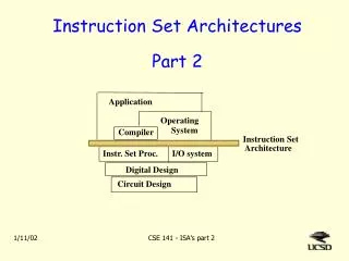
Instruction Set Architectures
Instruction Set Architectures. Science can amuse and fascinate us all, but it is engineering that changes the world. Use and Distribution Notice. Possession of any of these files implies understanding and agreement to this policy.

Instruction Set Architectures
E N D
Presentation Transcript
Instruction Set Architectures Science can amuse and fascinate us all, but it is engineering that changes the world.
Use and Distribution Notice • Possession of any of these files implies understanding and agreement to this policy. • The slides are provided for the use of students enrolled in Jeff Six's Computer Architecture class (CMSC 411) at the University of Maryland Baltimore County. They are the creation of Mr. Six and he reserves all rights as to the slides. These slides are not to be modified or redistributed in any way. All of these slides may only be used by students for the purpose of reviewing the material covered in lecture. Any other use, including but not limited to, the modification of any slides or the sale of any slides or material, in whole or in part, is expressly prohibited. • Most of the material in these slides, including the examples, is derived from Computer Organization and Design, Second Edition. Credit is hereby given to the authors of this textbook for much of the content. This content is used here for the purpose of presenting this material in CMSC 411, which uses this textbook.
Instructions and Instruction Sets • Each computer uses a certain language – each individual command (a word in the computer’s language) is called an instruction. • All of the instructions that a specific computer understands is called the instruction set. • There are multiple machine languages (instruction sets). While each is different, reflecting the design choices made during its construction, most instructions sets are similar. • Throughout this course, we will study the MIPS instruction set, with occasional comparisons to others. MIPS-based microprocessors are currently used by Silicon Graphics/SGI, NEC, and Cisco Systems (among others).
At the Beginning: Adding • The most basic instruction for every computer is that which performs addition. • The MIPS instruction for adding numbers is quite simple… add a, b, c • This instruction tells the computer to add the two variables b and c and to put the sum in the variable a. • This syntax is fixed … the add instruction in MIPS always takes two operands and produces the result.
Adding More than Two Numbers • Since the instruction format for adding is fixed, multiple instructions would need to be used to add more than two numbers. For instance, to add b, c, d, and e, putting the result in a… • The sharp symbol (#) delimits a comment. They are ignored by the computer. A comment in this language always ends at the end of the line. Also note that one and only one command can appear on a line. add a, b, c # sum of b & c is now stored in a add a, a, d # sum of b, c, & d is now stored in a add a, a, e # sum of b, c, d, & e is now stored in a
Fixed Operands: A Design Principle • Addition naturally favors three arguments, two operands and the sum. • Hardware for a fixed number of operands is much less complex than hardware that could support a variable number of operands (it’s always easier to do two rather than to do one, two, three, or any other number). • This gives rise to one of the cardinal rules of computer design… Simplicity favors regularity.
C to Assembler:A Basic Example • A compiler transforms a high-level language (like C) program into assembly language (what we have just seen). • A simple C program… a = b + c; d = a – e; … becomes a simple assembly language program… add a, b, c sub d, a, e
C to Assembler:A More Complex Example • A more complex example simple C statement… f = (g + h) – (i + j); … also becomes a fairly simple assembly language program. Here, we need some temporary storage, so let’s call these temporary variables t0 and t1 (there’s a reason for those names - we’ll get to that in a bit)… add t0, g, h # temp var t0 = g + h add t1, i, j # temp var t1 = i + j sub f, t0, t1 # f = to – t1
Registers • So far, we have used the non-descriptive term variable for the operands to our instructions. • At the assembly level, the operands of arithmetic instructions must be located in registers. • Registers are one of the fundamental concepts of computer architecture – they are high speed memory locations located on the same die as the microprocessor. They are directly addressable by the CPU. • The size of registers varies based on the instruction set – MIPS registers are 32 bits.
Register Limitations General Purpose Registers These are registers that are used for normal instructions – such as arithmetic operands. Non GP registers would be registers like the stack pointer, which contains the location of the system stack data structure. • There are typically a small amount of registers in a CPU… • MIPS has 32 32-bit general purpose registers. • Intel IA-32/x86 has 4 32-bit general purpose registers. • This (severe) limitation on the number of registers is typically done for two reasons… • Speed – smaller is normally faster • Cost – Registers are expensive • Modern computer designs have seen an explosive growth in general purpose registers… • Intel IA-64 has 128 64-bit general purpose registers.
Loading Information into Registers • Since all operands for arithmetic operands must be in registers, there needs to be a way to put information from main memory into a register. • In MIPS, this is accomplished using the load-word instruction (lw). The operands for this instruction are the name of the register to be loaded, and a constant followed by a register. • The memory location to load the value from is formed by adding the constant to a pointer contained in the last register.
Memory Addressing • Memory is modern microprocessors is byte addressable. That means that each individual byte can be specified by a memory address. • Each microprocessor has the concept of a word – this is the “preferred size” of data values for this architecture • A MIPS word is 32 bits. • An Intel IA-32/x86 word is 32 bits. • An Intel IA-64 word is 64 bits. • Most architectures enforce alignment restrictions – each word access must be at an address that is a multiple of the word size.
Alignment Restrictions • For example, a word can be found at memory locations 0, 4, 8, and so forth. • It is not legal to attempt to access a word at location 3. Location 20 Location 16 Location 12 Location 8 Location 4 Location 0 32 bits
Memory Address Space • The entire memory that is addressable by a microprocessor is referred to as its address space. • MIPS has a 32-bit address space. That means that all memory addresses are 32-bits long. This allows a maximum of 232 memory locations (remember each memory location is a byte – this is byte addressable memory). This means that 32-bit microprocessors can address 4 GB of memory. • The first (lowest) byte address is 0. • The last (highest) byte address is 4294967295.
The Load-Word Instruction • Consider the C language statement… g = h + A[8]; • We need to get the value stored in main memory at location 8 in the array A into a register in order to perform this instruction. If the base address of A is in $s3, this can be accomplished using the load-word instruction… lw $t0, 8($s3) …now that the value A[8] is in register t0, we can perform the addition… add $s1, $s2, $t0 #g = h + A[8]
Memory Layout: Endianness • One design decision faced by every microprocessor design must decide how to store multibyte values in memory. • Big endian processors store the leftmost (highest order) byte at the actual address of the value – little endian processors store the rightmost (lowest order) byte at the actual address of the value. • For example, the value 00000000 11111111 01010101 10101010 stored at location 1024… Location 1027 10101010 Location 1027 00000000 Location 1026 01010101 Location 1026 11111111 Location 1025 11111111 Location 1025 01010101 Location 1024 00000000 Location 1024 10101010 Big Endian Little Endian MIPS is big endian.
Revisiting the Load-Word Instruction • Looking again at the C language statement… g = h + A[8]; • We need to get the value stored in main memory at location 8 in the array A into a register in order to perform this instruction. Assuming A is an integer array and since integers are 32 bits in the MIPS architecture, the offset must be 4 x 8 = 32, since each entry in A is four bytes big and memory is byte addressable. We now have the load-word instruction… lw $t0, 32($s3)
The Store-Word Instruction • We have an instruction to load a value from memory into a register – now we need an instruction to take value from a register and copy it into memory. • This is accomplished using the store-word (sw) instruction, which has the same syntax as the load-word instruction.
Store-Word Example • For example, consider the C statement… A[12] = h + A[8]; • Assuming A is an array of 100 integers, the base address of A is stored in register $s3, and the variable h is already in register $s2, this statement could be implemented in MIPS assembly language as… lw $t0, 32($s3) #$t0 <= A[8] add $t0, $s2, $t0 #$t0 <= h+A[8] sw $t0, 48($s3) #A[12] <= $t0
Machine Instructions • So how are these instructions actually represented in the computer? • Like everything else … as a number. • In fact, each portion of an instruction is usually represented as a number and then the numbers are abutted together to form one instruction. • So far we have used registers like $s2 and $t0. These names are for our benefit … the CPU only understands numbered registers. We normally use a convention for name->number register mappings. • So far we have the s registers and the t registers (what the s and t represent will be discussed soon). In MIPS design, $s0->$s7 map to registers 16->23 and $t0->$t7 map to registers 8->15.
Instruction Format: R-Type • In the MIPS architecture, all instructions are 32 bits wide. The layout of these bits is known as the instruction format. • The addition and subtraction instructions are considered R-type (R for register) instructions in MIPS – they follow a standard format, common among all R-type instructions… opcode rs rt rd shamt funct • Opcode – This is the basic operation – what this instruction? • Rs – This is the first operand register. • Rt – This is the second operand register. • Rd – This is the destination register. • Shamt – This is the shift amount – it is only used in shift instructions which will be discussed at a later point. • Funct – This is the function (or function code). This selectes the specific variant of the operation (represented in the opcode) that is desired.
Instruction Formats • Remember our first design principle, simplicity favors regularity – all MIPS instructions are 32 bits and all register based instructions use the common R-type format. • Ideally, all instructions would use the same format. However, this is not always possible – how would one encode a data transfer (lw/sw) instruction using a R-type instruction format? • Since we need a (potentially large) offset encoded in the instruction and only two registers, the R-type format is not ideal.
Instruction Format: I-Type • This leads to another design principle… Good design demands good compromises. • Data transfer instructions are encoded in MIPS using the I-type instruction format… opcode rs rt address 6 bits 5 bits 5 bits 16 bits • Opcode – This is the basic operation – what this instruction? • Rs – This is the first operand register (the base address). • Rt – This is the destination register (loaded into or stored from). • Address – This is the offset for the instruction. So, lw/sw instructioncs can reference a region +/- 215 (32768) bytes from the base address.
MIPS Opcodes • Note that the R-type and I-type formats are similar (they both start with the opcode and then the registers). Each opcode has a specific instruction format and the CPU can look at the opcode to see what format the rest of the instruction is in. • Let’s look at how the four instructions we have been looking at are encoded… reg= register number, NA=fields does not appear in this instruction format, addr=16 bit address/offset
C -> Assembly -> Machine • Let’s consider this C statement… A[300] = h + A[300]; • Assuming $t1 has the base address of A and $s2 corresponds to h, this statement can be compiled into MIPS assembly… lw $t0, 1200($t1) add $t0, $s2, $t0 sw $t0, 1200($t1) • We can then express the assembly language in machine language (let’s start with decimal numbers)…
C -> Assembly -> Machine • Now that we have the machine instructions… …we can express our instructions in binary, just like they are stored in the computer…
C -> Assembly -> Machine A[300] = h + A[300]; lw $t0, 1200($t1) add $t0, $s2, $t0 sw $t0, 1200($t1) 10001101001010000000010010110000 00000010010010000100000000100000 10101101001010000000010010110000
The Stored Program Concept • So, programs are made up of instructions and instructions are simply numbers – programs are just numbers stored in memory. • This means that the same memory can contain program source code, the compiled machine code, the data being used, created, and manipulated by the program, and even the compiler used to compile the program (it’s all numbers!). M e m o r y A c c o u n t i n g p r o g r a m ( m a c h i n e c o d e ) This is known as the stored program concept. E d i t o r p r o g r a m ( m a c h i n e c o d e ) C c o m p i l e r ( m a c h i n e c o d e ) P r o c e s s o r P a y r o l l d a t a B o o k t e x t S o u r c e c o d e i n C f o r e d i t o r p r o g r a m
Decision Making:Branching Instructions • Computers are capable of making decisions – a capability that is frequently used in programming languages using the if statement. • The MIPS instruction set supports decision making using two conditional branch instructions. Both of these instructions involve two registers and a label. • The branch-if-equal (beq) instruction goes to the labeled point if the two registers contain the same value… beq $s1, $s1, LABEL1 • The branch-if-not-equal (bne) instruction goes to the labeled point if the two registers do not contain the same value… bne $s2, $s2, LABEL2
Labels • Remember, program instructions are stored in memory, just like data. The label used in the conditional branch instructions is simply a name for a specific memory address (that contains the instruction that should be executed next if the branch is taken). • The compiler will often generate labels where they are needed (often in places that you would not think of). This is one (of the many) benefits of programming in high-level languages. • This label is converted into an actual address when the program is converted from assembly language to machine language (this is normally done by a program known as an assembler).
Compiling if-then-else Statements • If-then-else statements compile nicely with beq and bne instructions. • For example, let’s compile the statement… if (i==j) f=g+h; else f=g-h; • Assume f->i are stored in $s0->$s4. This can be compiled into MIPS assembly language quite easily… bne $s3, $s4, Else add $s0, $s1, $s2 j Exit Else: sub $s0, $s1, $s2 Exit: The jump (j) instruction is an unconditional branch. It simply goes to the specified label/address.
Compiling Loops • Conditional branches are also useful for loops. • For example, let’s compile the loop… while (save[i] == k) i += j; • Assume i,j,k are in $s3,$s4,$s5 and the base address of the integer array save is in $s6. Let’s compile… Loop: add $t1, $s3, $s3 # temp = i * 2 add $t1, $t1, $t1 # temp = i * 4 add $t1, $t1, $s6 # addr of save[i] in $t1 lw $t0, 0($t1) # load save[i] into $t0 bne $t0, $s5, Exit # check loop condition add $s3, $s3, $s4 # if statement j Loop # we’re not done yet Exit:
The Zero Register and the set-on-less-than Instruction • MIPS includes the set-on-less-than (slt) instruction, which sets the destination register to one if the first operand register is less than the second operand register, zero otherwise… slt $t0, $s0, $s1 #t0 gets 1 if $s0<$s1, 0 else • Using only the slt, beq, and bne instructions, a compiler can produce any conditional expression (<, >, ==, !=, <=, >=). Note that sometimes this requires the value zero…the MIPS register $zero (register 0) is a zero bucket … it always contains a zero and writing anything to it simply discards the write.
Computer Hardware Function Support • Most modern high-level languages employ the concept of a function (or procedure or method). • When a function is called, there are generally six steps which are performed by the computer… • Parameters are placed somewhere that the called function can access them. • Control is transferred to the called function. • Storage resources needed in the called function are acquired. • The called function’s task is performed. • The return value is placed somewhere that the calling function can access it. • Control is transferred back to the point of origin.
In/Out Registers • As already discussed, registers are the fastest place to store information. • The MIPS architecture allocates seven of its registers for function calling… • $a0 -> $a3 are argument registers – they are used to pass data into a function. • $v0 -> $v1 are return registers – they are used to pass data out of a function. • $ra is the return address register – this is used to store a pointer to the point of origin (the place where the function was called; this is used to jump back to after the called function completes).
Function Calling • Functions are typically called in the MIPS architecture using the jump-and-link (jal) instruction. This instruction takes one argument, the memory address that the function begins at. • Upon execution, control is passed to the function entry point. The return address is automatically stored in the $ra register – this is the address that will be jumped to after the function completes; it is the address of the instruction right after the jal instruction. • This function is referred to as CALL in other popular instruction sets.
The Program Counter • For all of this to work, the address of the current instruction must be stored somewhere (how about a register?). • This is done in MIPS using the $pc (or PC) register – PC stands for program counter. This is also referred to as an instruction pointer. • Therefore, when a jal instruction is encountered (the PC points to a jal instruction), PC+4 is stored in $ra and PC changes to the memory address specified in the jal instruction. $pc 00001348 add $t0, $t0, $t0 0000134C jal 00001D60 00001350 add $t1, $t1, $t1 00001348 0000134C 00001D60 $ra 00001350
Returning from a Function • So once we are in a function and we’re all done, how do we get back? • The return address has been stored in the $ra register, so we simply need to jump to it. • This can be accomplished using the MIPS jump-to-register (jr) instruction. This instruction takes one parameter, the register that contains the address to jump to. • Since the $ra register has the return address, the end of the function is very simple… jr $ra
Function Call Flow • The calling function (the caller) puts input parameters for the called function (the callee) into registers $a0->$a3. • It then uses the jal instruction to jump to the other function’s entry point. • The callee performs the required function and puts the results into registers $v0->$v1. • It then returns to the next instruction in the caller by using the jr instruction and the $ra register. jal address jr $ra
Register Spilling • A function call should “cover its own tracks.” It should not alter the register contents of the calling function. • So, if the called function needs more than the $a0->$a3 and $v0->$v1 registers, some registers must be spilled. This means that the register contents are copied into memory, the registers are used, and then the original contents are restored from memory. • The ideal data structure for spilling registers is a stack. This is a basic last-in-first-out data structure.
Stack Layout H i g h a d d r e s s • For instance, if a function needs to use $t1, $t0, and $s0, those registers must be spilled while in the called function. • In this diagram, (a) shows the stack before the function call, (b) shows the stack during the function call, and (c) shows the stack after the function call. $ s p $ s p C o n t e n t s o f r e g i s t e r $ t 1 C o n t e n t s o f r e g i s t e r $ t 0 $ s p C o n t e n t s o f r e g i s t e r $ s 0 L o w a d d r e s s a . b . c .
Stack Layout – The Details • The stack is a data structure that is typically managed by the program with some assistance from the hardware. • In MIPS, one of the registers, the stack pointer ($sp) is reserved for storing the address of the most recently allocated address in the stack (where did the last thing that was put on the stack end up in memory?). • The stack pointer is adjusted by one word for each register that is spilled onto the stack (remember, a word in MIPS is 32 bits, the size of a register).
Stack Operations • Placing something on the stack is known as pushing it onto the stack. • Removing something from the stack is known as popping it off of the stack. • Stacks normally grow down – they start at higher memory addresses and each push gets stored at a lower memory address. • Each push moves the stack pointer down by 4 bytes ($sp = $sp – 4). • Each pop moves the stack pointer up by 4 bytes ($sp = $sp + 4).
Function Prologuesand Epilogues H i g h a d d r e s s $ s p $ s p C o n t e n t s o f r e g i s t e r $ t 1 C o n t e n t s o f r e g i s t e r $ t 0 $ s p C o n t e n t s o f r e g i s t e r $ s 0 L o w a d d r e s s a . b . c . sub $sp, $sp, 12 sw $t1, 8($sp) sw $t0, 4($sp) sw $s0, 0($sp) lw $s0, 0($sp) lw $t0, 4($sp) lw $t1, 8($sp) add $sp, $sp, 12 jr $ra This is the very beginning of the function. It is sometimes referred to as the function prologue. This is the very end of the function. It is sometimes referred to as the function epilogue.
Intel x86 and the Stack • Some microprocessors have more explicit support for the stack data structure. • Intel, for example, has PUSH and POP instructions in the x86 instruction set (both take a register as an argument… • PUSH copies that register onto the current end of the stack and moves the stack pointer down 32 bits. • POP copies the current piece of data on the stack into that register and moves the stack pointer up 32 bits. sub $sp, $sp, 12 sw $t1, 8($sp) sw $t0, 4($sp) sw $s0, 0($sp) PUSH EAX ($t1) PUSH EBX ($t0) PUSH ECX ($s0) MIPS x86
Register Semantics So, in our previous example, we did not need to spill $t0 and $t1, only $s0. • The MIPS $t# registers are known as temporary registers. They are just like temporary variables – their results are no longer necessary upon the computation is complete. • Therefore, MIPS provides two categories of registers with different semantics… • $t0->$t9 – these are 10 temporary registers that are not preserved by the called function on a function call (their values can change within the called procedure and are not restored prior to returning). • $s0->$s7 – these are 8 saved registers that are preserved by the called function (if their values are changed within the called procedure, the original values must be restored prior to returning).
If there is a jump-and-link instruction in this function body, we need the sw and lw instructions involving $ra. If there are no function calls in the body, they are not needed. Nested Procedures • So, when a procedure gets called, the jal instruction saves the return address into the $ra register. • If the called procedure calls another procedure, how is this accounted for? • Well, the $ra value must be spilled before the jal instruction is executed (otherwise, the first return address would be overwritten and lost). sub $sp, $sp, 16 sw $ra, 12($sp) sw $t1, 8($sp) sw $t0, 4($sp) sw $s0, 0($sp) … function body … lw $s0, 0($sp) lw $t0, 4($sp) lw $t1, 8($sp) lw $ra, 12($sp) add $sp, $sp, 16 jr $ra
Local Data • The stack is also used for function local storage (arrays, variables, structures, and so forth that are local to the function). • The segment of the stack that is used by a function (including saved/spilled registers and any local variables) is called the stack frame. • To keep track of all of this, MIPS uses a second register to keep track of the stack, the frame pointer ($fp). This register points to the first word of the current function’s stack frame.
H i g h a d d r e s s $ f p $ f p $ s p $ s p $ f p S a v e d a r g u m e n t r e g i s t e r s ( i f a n y ) S a v e d r e t u r n a d d r e s s S a v e d s a v e d r e g i s t e r s ( i f a n y ) L o c a l a r r a y s a n d s t r u c t u r e s ( i f a n y ) $ s p L o w a d d r e s s b . c . a . The Frame Pointer • Here, (a), (b), and (c) represent the stack before, during, and after the function call. • Note that the frame pointer points to the first word of the stack frame and the stack pointer points to the top of the stack.
$ f p S a v e d a r g u m e n t r e g i s t e r s ( i f a n y ) S a v e d r e t u r n a d d r e s s S a v e d s a v e d r e g i s t e r s ( i f a n y ) L o c a l a r r a y s a n d s t r u c t u r e s ( i f a n y ) $ s p Accessing Data on the Stack • Looking at the stack… • Normally saved registers, including the $ra, are accessed relative to the frame pointer. • Local variables are normally referenced relative to the stack pointer (as we sometimes do not know at compile time how many local variables might be pushed onto the stack and only $sp moves with each stack push). • If there are no local variables, the frame pointer is not normally used.