Lesson 4: Visual Aids to Navigation
Lesson 4: Visual Aids to Navigation . Learning Objectives:. Upon completion of this lesson, the student will: Be familiar with the shapes and lights of the International Association of Lighthouse Authorities (IALA) Combined Cardinal and Lateral System of buoyage.
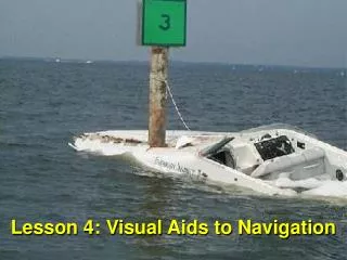

Lesson 4: Visual Aids to Navigation
E N D
Presentation Transcript
Learning Objectives: Upon completion of this lesson, the student will: • Be familiar with the shapes and lights of the International Association of Lighthouse Authorities (IALA) Combined Cardinal and Lateral System of buoyage. • Comprehend the use of buoys and beacons during piloting.
Learning Objectives: Upon completion of this lesson, the student will: • Comprehend the identifying characteristics and significance of lighted aids to navigation and buoys. • Apply correct procedures to identify and determine the computed visibility of a navigational light.
Significance of Nav Aids • Nav Aid: Any device external to a vessel or aircraft intended to assist in determining position and safe course, or to warn of dangers or obstructions.
Use of Buoys/Beacons in Piloting • The first objective upon sighting a NAVAID is to identify it. • After PID - make use of it • Use fixed aids to navigation and charted structures for shooting LOP’s whenever possible • Bearings to buoys may be used to helpclarify the navigation picture when no other objects are available.
Systems of Buoyage • Two general systems: • Lateral – Location of buoy or beacon indicated direction of danger it marks relative to the course that should normally be followed • Cardinal – location of buoy indicated approximate true bearing of safe water from the danger it marks
Lateral Systems of Buoyage • Lateral Systems of Buoyage • Method: indicate the direction of danger relative to the course that should normally be followed. • Uses: • Indicate sides or junctions of navigable channels • Indicate the safe side on which to pass a hazard • Mark the approx. centerline of wide bodies of water
Lateral Systems • US Lateral System “IALA B” • Red buoys mark the starboard (right) side of channels • When returning from seaward • Green buoys mark the port (left) side of channels • When returning from seaward • Uniform Lateral System “IALA A” • The opposite of above
International Association of Lighthouse Authorities (IALA) Region “A” Region “B” Region “B” • Japan • So. Korea • Philippines 2.1-11
Buoy and Daymark Shapes • Shape Assists in Easy Identification. • Assigned Certain Colors for Lateral Use. • Remember : COLOR Identifies Use.
Cardinal System of Buoyage • Uniform Cardinal System of Buoyage • Method: Used to indicate the approximate true bearing of safe water from the danger it marks. • Uses: • Mark offshore rocks, shoals, and islets. • Mark dangers in and near the open sea.
Cardinal Buoys The North cardinal buoy is black on top and yellow on bottom. The safe water lies to the north of this buoy.
Cardinal Buoys The East cardinal buoy is black with a yellow band. The safe water lies to the east of this buoy.
Cardinal Buoys The South cardinal buoy is yellow on top and black on bottom. The safe water lies to the south of this buoy.
Cardinal Buoys The West cardinal buoy is yellow with a black band. The safe water lies to the west of this buoy.
Cardinal Marks • Used in Conjunction With Compass to Mark Best Water. • Yellow and Black in Color. • Two Triangles for Topmark.
Isolated Danger Mark • On or above an isolated danger • Red and Black color • Topmark: 2 black vertical spaced balls • If lighted: Flashing (2) white light.
Special Marks • Used to identify special areas: Military exercise, traffic separation scheme, etc. • Color is yellow
Special Buoys • Used to mark: • Prohibited areas • Limits of fish traps • Cable crossings • Anchorages • Color is yellow • Usually unlighted
Buoy Positions • Position on chart is only an approximate position • Anchored to sea bottom. • Can drift off station • Not to be used to obtain a fix!
Beacons (Daymarkers) • Permanently fixed aids • Size from Lighthouses to small day boards • Readily visible and easily identified
RACON Buoys • RACON’s are used in the U.S. for the following: • to identify aids to navigation, both seaborne (e.g. buoys) and land-based (e.g. lighthouses) • to identify landfall or positions on inconspicuous coastlines • to indicate navigable spans under bridges • to identify offshore oil platforms and similar structures
PID Criteria: DAYTIME Location Shape Color Scheme Auxiliary features Special Markings NIGHT Phase characteristic Period Color Positive Identification of Navigation Aids
Phase Characteristics of NAVAIDS • Fixed (F.) - Shines with steady, unblinking intensity. • Flashing (Fl.) - Appears as a single flash at regular intervals; the duration of the light is always less than the duration of darkness. Flashing lights will not flash more than 30 times per minute. • Quick Flashing (Qk.Fl.) - Similar to a flashing light, but it shows more frequently to indicate a greater degree of cautionary significance. The duration of flash is less than the duration of darkness, and the light will flash at least 60 times per minute.
Phase Characteristics of NAVAIDS • Interrupted Quick Flashing (I.Qk.Fl.) - A light that quick flashes six times, followed by a time of darkness, with a standard period of ten seconds. • Group Flashing (Gp.Fl.) - Shows groups of two or more flashes at regular intervals. • Morse Code • Occulting
Chart Symbology for Lighted NAVAIDS • Lighted Navaids: • Lighted navaids have purple exclamation point ! or 1/8” purple circleover black dot. • Floating Navaids: • Fixed Navaids in ROMAN text • Floating Navaids in italics text • Flashing Navaids: • Numbers indicate patterns of light flashes • Occulting: numbers indicate the pattern of eclipses • eg. F Gp Fl (2+3) or Gp Occ (2+3)
Special Purpose Lights • Alternating Lights • change color following a regular pattern • airport beacons, harbor entrance lights
SECTOR LIGHTS Sector limits are expressed in degrees true as observed from a vessel, not from the light! • Red- Marks Danger Areas. • Green - Marks Turning Points or Best Water Areas. • White- Marks Good Water.
Ranges • Used to mark the center of the channel. • Consist of two fix dayboards some distance apart. The aft one is always higher than the front marker. • Color varies: Primary International Orange and White.
RANGES • Colors Various Are Listed Above. • Alignment Is Shown on the Left.
Determining the Computed Visibility of a NAVAID • Purpose: To be able to determine, in advance, when you should expect to gain or lose sight of a navaid during a coastal transit. • Computed visibility = The maximum distance at which a light can be seen given the current meteorological conditions. NOTE: Computed visibility Meteorological Visibility
Determining the Computed Visibility of a NavAid • Horizon distance = the LOS from a position above the earth’s surface to the visual horizon. • Geographic range = the maximum distance that a light may be seen in perfect visibility by an observer’s eye who is at sea level. • Computed range = the distance at which a light could be seen in perfect visibility (taking into account elevation, observer’s height of eye, and the curvature of the earth). CR = Horizon Distance + Geographic Distance
Determining the Computed Visibility of a NavAid • Luminous range = the maximum distance at which a light may be seen under under the current meteorological conditions. • Nominal range = a special case of the luminous range. It is the distance a light could be seen in “clear” weather. Also called the charted range. Appox 10 nms. • Computed visibility = The maximum distance at which a light can be seen in the current meteorological conditions.
Determining the Computed Visibility of a NAVAID First: Obtain the light’s intensity, its elevation above water, and the luminous range of the light from the luminous range diagram.
Second: Find the geographic range of the light by adding together the two horizon distances of both the light and the observer as follows (using Table 12 on p. 94 in Hobbs):
Determining the Computed Visibility of a NavAid • The first step in using the Light List or List of Lights is to determine the luminous range from the luminous range diagram (Appendix A / shown in Hobbs, p. 92). • The luminous range can be determined by entering the diagram at the top or bottom with the given nominal range.
Follow the nominal range value vertically until the appropriate visibility curve is intersected, then read the corresponding luminous range from the left or right hand side of the diagram. • In our example, the light has a nominal range of 23 nm in 5 1/2 nm of visibility, so the corresponding luminous range is 15 nm. • NOTE: the nominal range and luminous range are identical in 10-mile visibility.
Visual Navigation Aids • Final: compare the geographic range to the luminous range. The shorter range represents the computed visibility. The light has a corresponding luminous range of 15 nm and a geographic range of 20 nm. Therefore the computed visibility would be equal to the luminous range which is 15 nm.
Meteorological Optical range Table Code # Weather Yards/NM • 0 Dense Fog < 50 • 1 Thick Fog 50-200 • 2 Moderate Fog 200-500 • 3 Light Fog 500-1000 • 4 Thin Fog .5-1 NM • 5 Haze 1-2 NM • 6 Light Haze 2-5.5 NM • 7 Clear 5.5-11 NM • 8 Very Clear 11-27 NM • 9 Exceptionally Clear Over 27 NM
horizon 100 ft ht of light Visual Navigation Aids 11.7 NM * geographic range in miles ** horizon distance in miles