Transducers
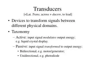
Transducers. [<Lat. Trans , across + ducere , to lead]. Devices to transform signals between different physical domains. Taxonomy Active: input signal modulates output energy; e.g. liquid crystal display. Passive: input signal transformed to output energy;

Transducers
E N D
Presentation Transcript
Transducers [<Lat. Trans, across + ducere, to lead] • Devices to transform signals between different physical domains. • Taxonomy • Active: input signal modulates output energy; e.g. liquid crystal display. • Passive: input signal transformed to output energy; • Bidirectional, e.g. motor/generator; • Unidirectional, e.g. photodiode
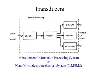
Signal domains • Signals may occur in many physical forms • Examples • Electrical signals on wires • Sound in free air • Light fields in free space • Transducers connect signal domains • input signals of one physical form • produce signals in a different physical form.
Signals, power and energy • Physical signals are carried by energy • Energy = force x distance (mechanical) [Joules] • May take many equivalent forms. • Within a domain: potential vs kinetic; • In different domains: electrical, nuclear, heat, etc. • Is conserved: can transform but not create or destroy. • Power = time derivative of energy [Watts] • Signal strength is a measure of signal power. • Signal to noise ratio is a ratio of powers. • A transducer receives signals in one domain and generates them in another.
Potential and kinetic energy • Potential energy is stored in reactive tension: • Voltage on a capacitor • Force compressing a spring • Kinetic energy is stored in reactive motion: • current in an inductor • velocity of a mass • Reactance types • Potential: voltage, force, electric field, etc.; • Kinetic: current, velocity, magnetic field, etc.
Voltage, current, force, &cet. • Power is expressible by pairs of variables: • Voltage and current, • Force and velocity, • Pressure and flow, etc. • These are potential-kinetic variable pairs in particular physical domains. • Each domain has an associated measure of impedance and its reciprocal, admittance, although nomenclature varies.
An electrostatic microphone Passive bidirectional transducer example • We first explore the physics relating voltage to pressure and current to volume-velocity. The result is non-linear. • We use small-signal assumptions to linearize the model. • We then represent these results in terms of two-port matrices which linearly relate variables between domains.
Parallel plate capacitor physics Consider a capacitor with fixed lower plate and movable upper plate, both of area A, separated by distance x. An amount Q of charge has been moved from one plate to the other, causing an electric field between them to develop a voltage V. The field of the lower plate acts on the charge of the upper plate to produce a force F on it. These effects provide the coupling between the electrical and mechanical domains.
Electric field of the lower plate Coulomb’s law in differential and integral forms: where D = eE, E is electric field, r is charge density, and e=8.85x10⁻¹² for air dielectric. The first integral is of the field normal to a closed surface, and the second is of the charge in the volume enclosed by the surface. Thus the field near a flat plate of area A with charge Q is,
Capacitance between the plates The definition of capacitance is Q=CV. The total field between the plates is the superposition of fields from both plates, or E=Q/eA. By the definition of voltage we have, The latter because the field between the plates is nearly uniform. From this we can obtain the formula for a parallel plate capacitor:
Force on the upper plate The field E from the charge on the lower plate exerts force on the charge Q on the upper plate which is negative: the latter because the field is nearly uniform over the plate area. Substituting for the electric field, we get a nonlinear force as a function of Q, which is always attractive.
Force - voltage relationship Let the total voltage VT = V0 + V, the sum of the bias and signal voltages respectively. Similarly, FT = F0 + F, where F0 is force due to the bias voltage alone and F is the signal force. Also, xT = x0 + x, where x0 is the plate separation at rest, and x is the signal displacement. The total force is, If the signal displacement x is held to zero, This is a non-linear relationship which is always attractive.
Linearizing the relationship This behavior can be “linearized” by assuming that Expanding FT and VT we make the approximation,
Two-port transducer matrices • Relate two input variables to two output variables. • The product of the input variables must be power • The product of the output variables must be power • Input and output variables may be in any domains • A microphone has inputs p and u, outputs V and I. • The hybrid, or h-parameter matrix H is written, * (See Hanspeter Schmid, “Tables: Two-Port Matrices,” people.ee.ethz.ch/~hps/publications/twoport.pdf )
The microphone’s T matrix It was convenient to use the H matrix because we could derive the behaviors of p and I when u and V were held fixed, respectively. It is also useful to have a transmission matrixT providing electrical outputs, given acoustic inputs. Conversion of the H matrix to the T matrix is a problem in linear algebra, the solution of which is,
The microphone’s Z matrix It is also sometimes useful to represent this as an impedance matrixZ facilitating impedance matching calculations at the electrical and acoustic ports. In this case, the solution is,