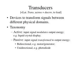
Transducers
Transducers. Ultrasound is produced and detected with a transducer, composed of one or more ceramic elements with electromechanical (piezoelectric) properties.

Transducers
E N D
Presentation Transcript
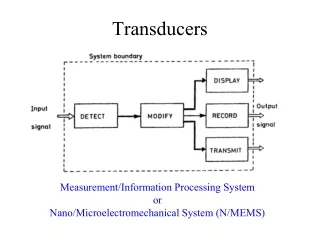
Ultrasound is produced and detected with a transducer, composed of one or more ceramic elements with electromechanical (piezoelectric) properties. • The ceramic element converts electrical energy into mechanical energy to produce ultrasound and mechanical energy into electrical energy for ultrasound detection.
Over the past several decades, the transducer assembly has evolved considerably in design, function, and capability, from a single-element resonance crystal to a broadband transducer array of hundreds of individual elements. • A simple single-element, plane-piston source transducer has major components including the • piezoelectric material, • marching layer, • backing block, • acoustic absorber, • insulating cover, • sensor electrodes, and • transducer housing.
Piezoelectric Materials • A piezoelectric material (often a crystal or ceramic) is the functional component of the transducer. • It converts electrical energy into mechanical (sound) energy by physical deformation of the crystal structure.
ConverseIy, mechanical pressure applied to its surface creates electrical energy. • Piezoelectric materials are characterized by a well-defined molecular arrangement of electrical dipoles (Fig. 16-9).
An electrical dipole is a molecular entity containing positive and negative electric charges that has no net charge. • When mechanically compressed by an externally applied pressure, the alignment of the dipoles is disturbed from the equilibrium position to cause an imbalance of the charge distribution.
A potential difference (voltage) is created across the element with one surface maintaining a net positive charge and one surface a net negative charge. • Surface electrodes measure the voltage, which is proportional to the incident mechanical pressure amplitude.
Conversely, application of an external voltage through conductors attached to the surface electrodes induces the mechanical expansion and contraction of the transducer element.
There are natural and synthetic piezoelectric materials. • An example of a natural piezoelectric material is quartz crystal, commonly used in watches and other time pieces to provide a mechanical vibration source at 32.768 kHz for interval timing. • This is one of several oscillation frequencies of quartz, determined by the crystal cut and machining properties.
Ultrasound transducers for medical imaging applications employ a synthetic piezoelectric ceramic, most often lead-zirconate-titanate (PZT). • The piezoelectric attributes are attained after a process of • Molecular synthesis, • Heating, • Orientation of internal dipole structures with an applied external voltage, • Cooling to permanently maintain the dipole orientation, and • Cutting into a specific shape.
For PZT in its natural state, no piezoelectric properties are exhibited; however, heating the material past its “Curie temperature” (i.e., 3280 C to 3650 C) and applying an external voltage causes the dipoles to align in the ceramic. • The external voltage is maintained until the material has cooled to below its Curie temperature. • Once the material has cooled, the dipoles retain their alignment.
At equilibrium, there is no net charge on ceramic surfaces. • When compressed, an imbalance of charge produces a voltage between the surfaces. • Similarly, when a voltage is applied between electrodes attached to both surfaces, mechanical deformation occurs.
The piezoelectric element is composed of aligned molecular dipoles.
Under the influence of mechanical pressure from an adjacent medium (e.g., an ultrasound echo), the element thickness • Contracts (at the peak pressure amplitude), • Achieves equilibrium (with no pressure) or • Expands (at the peak rarefactional pressure), • This causes realignment of the electrical dipoles to produce positive and negative surface charge.
Surface electrodes (not shown) measure the voltage as a function of time.
An external voltage source applied to the element surfaces causes compression or expansion from equilibrium by realignment of the dipoles in response to the electrical attraction or repulsion force.
Resonance Transducers • Resonance transducers for pulse echo ultrasound imaging are manufactured to operate in a “resonance” mode, whereby a voItage (commonly 150 V) of very short duration (a voltage spike of 1 msec) is applied, causing the piezoelectric material to initially contract, and subsequently vibrate at a natural resonance frequency. • This frequency is selected by the “thickness cut,” due to the preferential emission of ultrasound waves whose wavelength is twice the thickness of the piezoelectric material.
The operating frequency is determined from the speed of sound in, and the thickness of, the piezoelectric material. • For example, a 5-MHz transducer will have a wavelength in PZT (speed of sound in PZT is 4,000 m/sec) of
A short duration voltage spike causes the resonance piezoelectric element to vibrate at its natural frequency, fo, which is determined by the thickness of the transducer equal to 1/A.
To achieve the 5-MHz resonance frequency, a transducer element thickness of ½ X0.8 mm = 0.4 mm is required. • Higher frequencies are achieved with thinner elements, and lower frequencies with thicker elements. • Resonance transducers transmit and receive preferentially at a single “center frequency.”
Damping Block • The damping block, layered on the back of the piezoelectric element, absorbs the backward directed ultrasound energy and attenuates stray ultrasound signals from the housing. • This component also dampens he transducer vibration in create an ultrasound pulse width a short spatial pulse length, which is necessary to preserve detail along he beam axis (axial resolution).
Dampening of the vibration (also known as “ring-down”) lessens the purity of the resonance frequency and introduces a broadband frequency spectrum. • With ring-down, an increase in he bandwidth (range of frequencies) of he ultrasound pulse occurs by introducing higher and lower frequencies above and below the center (resonance) frequency.
The “Q factor” describes the bandwidth of the sound emanating from a transducer as • where fo is the center frequency and the bandwidth is the width of the frequency distribution.
A “high Q” transducer has a narrow bandwidth (i.e., very little damping) and a corresponding long spatial pulse length. • A “low Q” transducer has a wide bandwidth and short spatial pulse length.
Imaging applications require a broad bandwidth transducer in order to achieve high spatial resolution along the direction of beam travel. • Blood velocity measurements by Doppler instrumentation require a relatively narrow-band transducer response in order to preserve velocity information encoded by changes in the echo frequency relative to the incident frequency.
Continuous-wave ultrasound transducers have a very high Q characteristic. • While the Q factor is derived from the term qualityfactor, a transducer with a low Q does not imply poor quality in the signal.
Matching Layer • The matching layer provides the interface between the transducer element and the tissue and minimizes the acoustic impedance differences between the transducer and the patient. • It consists of layers of materials with acoustic impedances that are intermediate to those of soft tissue and the transducer material. • The thickness of each layer is equal to one-fourth the wavelength, determined from the center operating frequency of the transducer and speed of sound in the matching layer.
For example, the wavelength of sound in a matching layer with a speed of sound of 2,000 m/sec for a 5-MHz ultrasound beam is 0.4 mm. • The optimal matching layer thickness is equal to ¼l =¼ x 0.4 mm = 0. 1 mm. • In addition to the matching layers, acoustic coupling gel (with acoustic impedance similar to soft tissue) is used between the transducer and the skin of the patient to eliminate air pockets that could attenuate and reflect the ultrasound beam.
Nonresonance (Broad-Bandwidth) “Multifrequency” Transducers • Modern transducer design coupled with digital signal processing enables “multifrequency or “multihertz” transducer operation, whereby rhe center frequency can be adjusted in he transmit mode. • Unlike the resonance transducer design, the piezoelectric element is intricately machined into a large number of small “rods,” and then filled with an epoxy resin to create a smooth surface.
The acoustic properties are closer to issuethan a pure PZT material, and thus provide a greater transmission efficiency of the ultrasound beam without resorting to multiple matching layers. • Multifrequency transducers have bandwidths that exceed 80% of the center frequency.
Excitation of the multifrequency transducer is accomplished with a short square wave burst of 150 V with one to three cycles, unlike the voltage spike used for resonance transducers. • This allows the center frequency to be selected within the limits of the transducer bandwidth.
Likewise, the broad bandwidth response permits the reception of echoes within a wide range of frequencies. • For instance, ultrasound pulses can be produced at a low frequency, and the echoes received at higher frequency.
“Harmonic imaging” is a recently introduced technique that uses this ability; • lower frequency ultrasound is transmitted into the patient, and the higher frequency harmonics (e.g., two times the transmitted center frequency) created from the interaction with contrast agents and tissues, are received as echoes.
Native tissue harmonic imaging has certain advantages including greater depth of penetration, noise and clutter removal, and improved lateral spatial resolution.
Transducer Arrays • The majority of ultrasound systems employ transducers with many individual rectangular piezoelectric elements arranged in linear or curvilinear arrays. • Typically, 128 to 512 individual rectangular elements compose the transducer assembly. • Each element has a width typically less than half the wavelength and a length of several millimeters.
Two modes of activation are used to produce a beam. • These are the “linear” (sequential) and “phased” activation/receive modes.
Linear Arrays • Linear array transducers typically contain 256 to 512 elements; physically these are the largest transducer assemblies.
In operation, the simultaneous firing of’ a small group of 20 adjacent elements produces the ultrasound beam. • The simultaneous activation produces a synthetic aperture (effetive transducer width) defined by the number of active elements.
Echoes are detected in the receive mode by acquiring signals from mostof the transducer elements. • Subsequent “A-line” acquisition occurs by firing another group of transducer elements displaced by one or two elements.
A rectangular field of view is produced with this transducer arrangement. • For a curvilinear array, a trapezoidal field of view isproduced.
Phased Arrays • A phased-array transducer is usually composed of 64 to 128 individual elements in a smaller package than a linear array transducer. • All transducer elements are activated nearly (but not exactly) simultaneously to produce a single ultrasound beam.
By using time delays in the electrical activarion of the discrete elements across the face of the transducer, the ultrasound beam can be steered and focused electronically without moving the transducer. • During ultrasound signal reception, all of the transducer elements detect the returning echoes from the beam path, and sophisticated algorithms synthesize the image from the detected data.