TRANSDUCERS
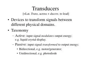
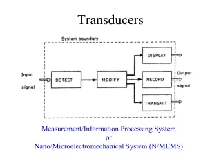
TRANSDUCERS. Introduction. Basically transducer is defined as a device, which converts energy or information from one form to another. These are widely used in measurement work because not all quantities that need to be measured can be displayed as easily as others.


TRANSDUCERS
E N D
Presentation Transcript
Introduction • Basically transducer is defined as a device, which converts energy or information from one form to another. • These are widely used in measurement work because not all quantities that need to be measured can be displayed as easily as others. • A better measurement of a quantity can usually be made if it may be converted to another form, which is more conveniently or accurately displayed.
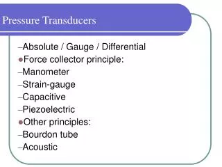
Introduction(cont’d) • For example, the common mercury thermometer converts variations in temperature into variations in the length of a column of mercury. Since the variation in the length of the mercury column is rather simple to measure, the mercury thermometer becomes a convenient device for measuring temperature. • Manometer, which detects pressure and indicates it directly on a scale calibrated in actual units of pressure.
Introduction(cont’d) • Thus the transducer is a device, which provides a usable output in response to specific input measured, which may be physical or mechanical quantity, property or condition. • The transducer may be mechanical, electrical, magnetic, optical, chemical, acoustic, thermal nuclear, or a combination of any two or more of these.
Mechanical transducers Advantages:- • simple and rugged in construction • cheaper in cost • accurate and • operate without external power supplies Disadvantage:- • poor frequency response • requirement of large forces to overcome mechanical friction • in compatibility when remote control or indication is required
ELECTRICAL TRANSDUCERS • Mostly quantities to be measured are non-electrical such as temperature, pressure, displacement, humidity, fluid flow, speed etc., but these quantities cannot be measured directly. Hence such quantities are required to be sensed and changed into some other form for easy measurement. • Electrical quantities such as current, voltage, resistance. inductance and capacitance etc. can be conveniently measured, transferred and stored, and therefore, for measurement of non-electrical quantities these are to be converted into electrical quantities first and then measured.
ELECTRICAL TRANSDUCERS(cont’d) • The function of converting non-electrical quantity into electrical one is accomplished by a device called the electrical transducer. • Basically an electrical transducer is a sensing device by which a physical, mechanical or optical quantity to be measured is transformed directly, with a suitable mechanism, into an electrical signal(current, voltage or frequency). • The production of these signals is based upon electrical effects which may be resistive, inductive, capacitive etc in nature.
BASIC REQUIREMENTS OF A TRANSDUCER The main function of a transducer is to respond only for the measurement under specified limits for which it is designed. It is, therefore, necessary to know the relationship between the input and output quantities and it should be fixed. Transducers should meet the following basic requirements:- • Ruggedness: It should be capable of withstanding overload and some safety arrangement should be provided for overload protection. • Linearity: Its input-output characteristics should be linear and it should produce these characteristics in symmetrical way.
Basic Requirements Of a Transducer (cont’d) • Repeatability: It should reproduce same output signal when the same input signal is applied again and again under fixed environmental conditions e.g. temperature, pressure, humidity etc. • High Output Signal Quality: The quality of output signal should be good i.e. the ratio of the signal to the noise should be high and the amplitude of the output signal should be enough. • High Reliability and Stability: It should give minimum error in measurement for temperature variations, vibrations and other various changes in surroundings.
Basic Requirements Of a Transducer (cont’d) • No Hysteretic: It should not give any hysteretic during measurement while input signal is varied from its low value to high value and vice-versa. • Residual Deformation: There should be no deformation on removal of local after long period of application. • Range: The range of the transducer should be large enough to encompass all the expected magnitudes of the measurand.
Basic Requirements Of a Transducer (cont’d) • Sensitivity: The transducer should give a sufficient output signal per unit of measured input in order to yield meaningful data. • Electrical Output Characteristics: The electrical characteristics-the output impedance, the frequency response, and the response time of the transducer output signal should be compatible with the recording device and the rest of the measuring system equipment. • Physical Environment:The transducer selected should be able to withstand the environmental conditions to which it is likely to be subjected while carrying out measurements and tests.
Basic Requirements Of a Transducer (cont’d) • Errors: The errors inherent in the operation of the transducer itself, or those errors caused by environmental conditions of the measurement, should be small enough or controllable enough that they allow meaningful data to be taken. • Good Dynamic Response: Its output should be faithful to input when taken as a function of time. The effect is analyzed as the frequency response.
Classification Of Transducers • The transducers may be classified in various ways such as on the basis of electrical principles involved, methods of application, methods of energy conversion used, nature of output signal etc. 1. On the basis of transduction principle involved: • Resistive • Inductive • Capacitive etc.
Classification Of Transducers(cont’d) • Primary and Secondary Transducers: Transducers, on the basis of methods of applications, may be classified into primary and secondary transducers. When the input signal is directly sensed by the transducer and physical phenomenon is converted into the electrical form directly then such a transducer is called the primary transducer.
2-Primary and Secondary Transducers(cont’d) • For example a thermistor used for the measurement of temperature fall in this category. The thermistor senses the temperature directly and causes the change in resistance with the change in temperature. When the input signal is sensed first by some detector or sensor and then its output being of some form other than input signals is given as input to a transducer for conversion into electrical form, then such a transducer falls in the category of secondary transducers.
Primary and Secondary Transducers(cont’d) • For example, in case of pressure measurement, bourdon tube is a primary sensor which converts pressure first into displacement, and then the displacement is converted into an output voltage by an LVDT. In this case LVDT is secondary transducer.
3-Active and Passive Transducers. • Transducers, on the basis of methods of energy conversion used, may be classified into active and passive transducers. Active transducers:- • Self-generating type transducers i.e. the transducers, which develop their output the form of electrical voltage or current without any auxiliary source, are called the active transducers. Such transducers draw energy from the system under measurement. Normal such transducers give very small output and, therefore, use of amplifier becomes essential. E.g. Thermocouple.
Active and Passive Transducers(cont’d) Passive transducers:- • Transducers, in which electrical parameters i.e. resistance, inductance or capacitance changes with the change in input signal, are called the passive transducers. These transducers require external power source for energy conversion. In such transducer electrical parameters i.e. resistance, inductance or capacitance causes a change in voltages current or frequency of the external power source. These transducers may draw sour energy from the system under measurement. Resistive, inductive and capacitive transducer falls in this category.
4-Analog and Digital Transducers • Transducers, on the basis of nature of output signal, may be classified into analog and digital transducers. Analog transducer:- • converts input signal into output signal, which is a continuous function of time such as thermistor, strain gauge, LVDT, thermo-couple etc. Digital transducer:- • converts input signal into the output signal of the form of pulse e.g. it gives discrete output.
Analog and Digital transducers(cont’d) • These transducers are becoming more and more popular now-a-days because of advantages associated with digital measuring instruments and also due to the effect that digital signals can be transmitted over a long distance without causing much distortion due to amplitude variation and phase shift. Sometimes an analog transducer combined with an ADC (analog-digital convector) is called a digital transducer.
5. Transducers and Inverse Transducers. Transducer:- • Transducer, as already defined, is a device that converts a non-electrical quantity into an electrical quantity. For example a thermo-couple, photoconductive cell, pressure gauge, strain gauge etc. Inverse transducer:- • An inverse transducer is a device that converts an electrical quantity into a non-electrical quantity. It is a precision actuator having an electrical input and a low-power non-electrical output.
Transducers and Inverse Transducers(cont’d) • For examples a piezoelectric crystal and transnational and angular moving-coil elements can be employed as inverse transducers. Many data-indicating and recording devices are basically inverse transducers. An ammeter or voltmeter converts electric current into mechanical movement and the characteristics of such an instrument placed at the output of a measuring system are important. A most useful application of inverse transducers is in feedback measuring systems.
DEFINITION • A strain gauge is an example of passive transducer that converts a mechanical displacement into a change of resistance. • A strain gauge is a thin wafer like device that can be attached to a variety of materials to measure applied strain.
WORKING • - The strain gauge is connected into a Wheatstone Bridge circuit. The change in resistance is proportional to applied strain and is measured with Wheatstone bridge.
TYPES OF STRAIN GAUGES • Unbonded metal strain gauges • Bonded metal wire strain gauges • Bonded metal foil strain gauges • Vacuum deposited thin metal film strain gauges • Sputter deposited thin metal film strain gauges • Semiconductor strain gauges
ADVANTAGES & DISADVANTAGES • Advantages: There is no moving part. It is small and inexpensive. • Disadvantages: It is non-linear. It needs to be calibrated.
APPLICATIONS • Residual stress and Vibration measurement, Torque measurement, Bending and deflection measurement, Compression and tension measurement, Strain measurement
CONTENTS: • LVDT • CONSTRUCTION • PRINCIPLE • OPERATION • USES
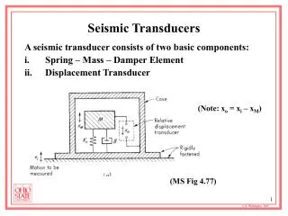
LINEAR VARIABLE DIFFERENTIAL TRANSFORMER (LVDT) • Linear variable-differential transformer is the most widely used Inductive transducer to translate linear motion into electrical signal.
A differential transformer consists of a primary winding and two secondary windings. The windings are arranged concentrically and next to each other. • A ferromagnetic core(armature) in the shape of a rod or cylinder is attached to the transducer sensing shaft. • The core slides freely within the hollow portion of the bobbin.
PRINCIPLE : • Any physical displacement of the core causes the voltage of one secondary winding to increase while simultaneously reducing the voltage in the other secondary winding. • The difference of the two voltages appears across the output terminals of the transducers and gives a measure of the physical position of the core and hence displacement.
working: • When the core is in the neutral or zero position and two secondary windings are equal and opposite and the net output is negligible. • By comparing the magnitude and phase of output with input source, the amount and direction of movement of core and hence displacement may be determined.
USES • The LVDT can be used in all applications where displacements ranging from fraction of a mm to few cm have to be measured. • Acting as a secondary transducer it can be used as a device to measure force, weight, pressure etc.
TORQUE It is defined as the force acting on a body which tends to produce rotation. Mathematically ,torque is given as : T = F x D Where, T = torque F = force D = perpendicular distance from the axis of rotation of the line of action of force A number of devices which can be used for the measurement of torque is : 1. Strain gauge torque meter 2. Inductive torque transducer 3. Magnetostrictive transducer 4. Digital methods
1. STRAIN GAUGE TORQUE METER :- The torque is given by the relation ; Where, G = modulus of rigidity measured in N/m². R = outer radius of the shaft measured in m. r = inner radius of the shaft measured in m. L = length of the shaft measured in m.
THEORY:- A strain gauge is generally measured by electrical means, In this arrangement , two strain gauges are subjected to tensile stresses while the other two experience Compressive stresses to indicated the torque. . The gauges must be at 45 with the shaft axis. Gauge 1 and 2 must be diametrically opposite , as must gauge 3 and 4 . ADVANTAGE :- 1. They are fully temperature compensated. 2. they give a maximum sensitivity for a given torque.
2. Inductive torque transducer In inductive torque transducer ,flange A carries a coil and flange B, an iron core. This core is move IN an OUT of the coil according to the relative displacement of the two flanges.
THEORY: The coil used an arm of A.C bridge . The displacement is depend upon torque. The bridge output can be directly calibrated to read the torque. The output of the A.C bridge is depend upon the inductance of the coil which in turn depends upon the position of core and hence on the displacement.
3. Magnetostrictive transducers These are based on the principle that the permeability of magnetic material changes when they are subjected to strain . The permeability decreases with positive strain and increases with Negative strain .
THEORY :- Magnetostrictive transducer is used for the measurement of torque. The inductance of one of the coil increases due to the increase in permeability. When an torque is applied, then bridge is balanced and two coil have equal inductance. When torque is applied , inductance of one coil increases whereas inductance of another coil is decreases and hence , bridge is unbalanced..
4. Digital methods Types:- 1. single toothed wheel system 2. Multi- toothed wheel system Single toothed wheel system :- Digital timing techniques are generally used for the determination of relative displacement between two flanges A and B .
THEORY :- When a torque is applied to the shaft, there is a relative there is a relative displacement between the two flanges , and a phase shift is produced between the pulses in the inductive transducer C and D . when these pulses are compared with the help of an electronic timer, a time interval will be displayed between the two pulses. these time interval is proportional to the relative displacement of the two flanges which in turn proportional to the torque. ADVANTAGE :- 1. Errors are eliminated. 2. There is no noise problem.
2.Multi toothed wheel system Multi –toothed wheels will replace the single –toothed wheels .
THEORY :- The transducer are generally magnetic or photoelectric. In this case, the output is perfectly sinusoidal . . The two outputs are exactly in phase of the two wheels are correctly. The output voltage progressively becomes out of phase as the torque increases because an increases in torque results in relative displacement of the two flanges.