Back Trajectory Techniques in Air Pollution
Back Trajectory Techniques in Air Pollution. Farhan Akhtar Benton Whitesides Bo Yan 11/19/2003 EAS 6792. D efinition. Trajectories: the paths of infinitesimally small particles of air as they move through time and space.

Back Trajectory Techniques in Air Pollution
E N D
Presentation Transcript
Back TrajectoryTechniques in Air Pollution Farhan Akhtar Benton Whitesides Bo Yan 11/19/2003 EAS 6792
Definition • Trajectories: the paths of infinitesimally small particles of air as they move through time and space. • Such fluid particles, ‘marked’ at a certain point in space at a given time, can be traced forward or backward in time along their trajectory. • Backward (back) trajectories: • indicate the past path of a particle • Forward trajectories: • indicate the future path of a particle
Example Back Trajectory 7-day Back trajectories from the ship (receptor) have been calculated using the HYSPLIT 4 model (HYbrid Single-Particle Lagrangian Integrated trajectory). receptor
Applications of Back Trajectories • Synoptic meteorology • Investigate air mass flow around mountains(Steinacker, 1984) • Climatology • Identify pathways of water vapor transport (D’Abreton and Tyson, 1996) or desert dust (Chiapello et al., 1997) • Environmental Sciences • Establish source-receptor relationships of air pollutants (Stohl, 1996a) • Law Enforcement • Combine with pollen measurements to find possible locations of marijuana cultivation (Cabezudo et al.,1997)
Calculation of the Back Trajectory X- the position vector during a time step dt resulting from the wind v; - mean wind velocity vector (no consideration the turbulent mixing in atmosphere)
Calculation of the Back Trajectory (cont’d) If known x0 at t0 :
Error Sources in the Computation of Back Trajectories • Wind field errors • In many cases, they are the largest single source of errors for back trajectory calculations. Wind field errors can be due to either analysis or forecast errors. • Starting position errors and amplification of errors • The starting positions of the trajectories are often not exactly known • Difficult to select start positions due to the differences between the model topography and the real topography • Back trajectory position errors can be strongly amplified in convergent flow.
Error sources for the computation of back trajectories (con’t) • Truncation errors • They come from the trajectory equation solution, which is approximated by a finite-difference scheme that neglects the higher order terms of Taylor series. In order to keep truncation errors negligible, a numerical scheme of high order using very short time steps is needed. • Interpolation errors • Due to the limit available wind data, wind speed must be estimated at the trajectory position. The interpolation errors will be caused during the process. • Errors resulting from assumptions regarding the vertical wind • Because there are no routine observation of vertical wing component w, Wind field of w can only gotten from meteorological model. So, it is less accurate than the horizontal wind fields.
Lagrangian Particle Dispersion Models (LPDM) • V - mean wind vector obtained directly from meteorological model • V’ - turbulent wind vector describing the turbulent diffusion of the tracer in the PBL.
Lagrangian box models • Similar to LPDM, changes in the concentrations in the box caused by chemical reactions and deposition are calculated. • No boundary conditions are required. • Applicable only at higher levels of the atmosphere • The most important boundary layer processes, such as the formation of nighttime reservoir layers or the rapid growth of the mixed layer depth in the morning, can be described with such models (Hertel et al., 1995),
Statistical analyses of trajectories • Flow Climatologies • Cluster analysis • Residence time analysis and conditional probability • Concentration fields • Redistributed concentration field • Inverse modeling
Accuracy • Measure of the integral effect of all errors • Determined by following the movement of conserved tracers: • Balloons • Stay at a constant pressure height • Do not measure vertical errors • Material Tracers • Conservative species are monitored. • Compare results with Meteorological measurements • Dynamical Tracers • Attempt to model vertical movement in the atmosphere • Potential temperature, isentropic potential vorticity
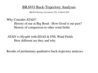
Examples Applications of Back-Trajectory Techniques Determination of Regional Sources of Winter Smoke Pollution in New Zealand Tajectory analysis of particulates in Big Bend national park
Determination of Regional Sources of Smoke Pollution in Winter • Night time burning of wood and coal in domestic fires created smoke pollution for the town of Christchurch, New Zealand. • In the evening, temperature inversions trap pollution close to the surface. • Burning created high concentrations of particulate matter from the ground to 10m. • Used back-trajectory models to determine origin and pathways of polluted parcels.
PM10 and CO Concentrations • Winter 1988-1999 averaged concentrations in Christchurch for a 24 hour period. • Reveals Diurnal cycle of PM10 peaking over night.
Region of Interest City of Cristchurch New Zealand • Plains to the North and West • Hills to the South • Water to the East
Complexities • Terrain creates complexity in low level flow. • On clear calm nights, radiative cooling of hill slopes causes cold air drainage into the region of interest.
Techniques • Only enough data to use simple back-trajectory techniques. • Lagrangian Kinematic Back-Trajectory Modeling techniques. • Regional Atmospheric Modelling System (RAMS) based on averaged nocturnal wind fields typically associated with high pollution events in the city (1995-2000).
Nested Grid Model • RAMS is a 3-D Nested Grid Model allowing focus on specific regions. • No vertical grid nesting- focus on lowest km of atmosphere (damping applied to higher altitudes).
Techniques • Models air flow of 4 Cases: No initial wind Weak NW wind Strong SW wind Moderate NE wind • Resolution: (Spatial 500m) (Temporal 15 mins) • Run times = 3pm to 3am • 2nd Order Turbulence Closure
Model Vs. Observations • Model recreation of the horizontal wind field compares well to actual observations. • Other methods of comparison included standard deviation & root-mean square. • Using these wind fields, back trajectories plotted for given endpoints.
Problems • Ignored particle settling rates. • Vertical velocities neglected (though realistic for night) • No examination of concentration changes in parcels during transport. • No consideration of sources of sinks during transport (chemical & photochemical reactions). • Synoptic events not considered
Back Trajectory Plots • Trajectory plots show parcel path across grid space from surrounding regions. • Urban area of Christchurch is represented by grid dots.
Results: No Initial Wind • Surface airflow dominated by local effects (cold air drainage from hills). • Air originates in plains and moves towards the city, except for near the hills where cold air drainage occurs.
Results: Strong SW Wind (10 m/s) • Gradient wind: -dominates transport, -turbulent mixing and -inhibits inversion • No impact from cold air drainage. • Air travels much farther.
Results: Light NW Wind • Similar to what happens with no initial wind. • Terrain dominates transport (cold air drainage). • Transport almost independent from wind. • Parcels move from hills into city. (As expected from cold air drainage)
Results: Moderate NE Wind • Very different from other cases • Air blowing on shore. • Seabreeze & orographic wind switch direction as drainage develops. • Air re-circulates over city allowing evening pollution buildup. • Hills less important.
3 Back Trajectories From NE Wind: • Note recirculation of parcels over the city with changing winds. • Grey dots indicate endpoints of each trajectory.
Implications & Conclusions • Cold Air Drainage allows leakage of southern hill pollutants into city and northern valleys overnight. • Drainage can be inhibited by stability. • Burning during winter (problematic months) should be restricted.
Background • Park has registered the poorest visibility in the western United States. • Since 1988, fine particulate matter and optical data has been collected in the park • The majority of the visibility degradation is due to sulfate particles. • Large coal-fired power plants are located over the border into Mexico. • Use a LPDM to determine the sources for these particulates
LPDM Inputs • The depth of the transport zone is set at the lowest inversion layer which meets these criteria: • height is at least 300 m above the ground • Potential temperature lapse rate of at least 5 K/km • Potential temperature is 2K greater at the top than at the bottom • If no inversion exists, 3000m is assumed • Horizontal winds are linearly interpolated from rawinsonde measurements • Computed backward in 6h time steps for a maximum of 120h (5 days)
Accuracy and Errors • Rainout and especially low inversion layers are not accounted for • Trajectories are aggregated over long time periods to attempt to minimize errors
Results • If over 80% of the trajectories calculated for a day came from one country, the day was assigned to that country. • 935 days from 10 years were analyzed • The model indicates that most particles (59%) came from Mexico.
Results by season Overall source attribution from 1989-1998
Results by season Overall source attribution for fine sulfur from 1989-1998
Results by season Overall source attribution for organic carbon from 1989-1998
References Gebhart, Kristi A., et al., Back-trajectory analyses of fine particulate matter measured at Big Bend National Park in the historical database and the 1996 scoping study. The Science of the Total Environment. Vol 276. Elsevier 2001. pp.185-204. Stohl, A. Computation, Accuracy and Applications of Trajectories- A Review and Bibliography. Atmospheric Environment. Vol 32. Pergamon 1998. pp. 947-966. Stohl, A., et. al. A replacement for simple back trajectory calculations in the interpretation of atmospheric trace substance measurements. Atmospheric Environment. Vol 36. Pergamon 2002. pp. 4635-4648. Sturman, A., P. Zawar-Reza. Aplication of back-trajectory techniques to the determination of urban clean air zones. Atmospheric Environment. Vol 36. Pergamon 2002. pp. 3339-3350.