Geometrical Optics
560 likes | 1.04k Vues
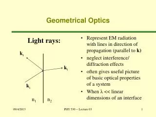
Geometrical Optics. Units . The Reflection of Light Forming Images with a Plane Mirror Spherical Mirrors Ray Tracing and the Mirror Equation The Refraction of Light Ray Tracing for Lenses The Thin-Lens Equation Dispersion and the Rainbow. The Reflection of Light.

Geometrical Optics
E N D
Presentation Transcript
Units • The Reflection of Light • Forming Images with a Plane Mirror • Spherical Mirrors • Ray Tracing and the Mirror Equation • The Refraction of Light • Ray Tracing for Lenses • The Thin-Lens Equation • Dispersion and the Rainbow
The Reflection of Light If a stone is dropped into a pond, circular waves emanate from the point where it landed. Rays, perpendicular to the wave fronts, give the direction in which the waves propagate.
The Reflection of Light As one moves farther from a point wave source, the wave fronts become more nearly flat.
The Reflection of Light The law of reflection states that the angle of incidence equals the angle of reflection:
The Reflection of Light Reflection from a smooth surface is called specular reflection; if the surface is rough, it is diffuse reflection.
Forming Images with a Plane Mirror Light reflected from the flower and vase hits the mirror. Obeying the law of reflection, it enters the eye. The eye interprets the ray as having had a straight-line path, and sees the image behind the mirror.
Forming Images with a Plane Mirror Properties of Mirror Images Produced by Plane Mirrors: • A mirror image is upright, but appears reversed right to left. • A mirror image appears to be the same distance behind the mirror that the object is in front of the mirror. • A mirror image is the same size as the object.
Forming Images with a Plane Mirror A corner reflector reflects light parallel to the incident ray, no matter the incident angle.
Spherical Mirrors A spherical mirror has the shape of a section of a sphere. If the outside is mirrored, it is convex; if the inside is mirrored, it is concave.
Spherical Mirrors Spherical mirrors have a central axis (a radius of the sphere) and a center of curvature (the center of the sphere).
Spherical Mirrors Parallel rays hitting a spherical mirror come together at the focal point (or appear to have come from the focal point, if the mirror is convex).
Spherical Mirrors This is a ray diagram for finding the focal point of a concave mirror.
Spherical Mirrors For a convex mirror, the focal length is negative, as the rays do not go through the focal point. The opposite is true for a concave mirror.
Spherical Mirrors We have made the assumption here that the rays do not hit the mirror very far from the principal axis. If they do, the image is blurred; this is called spherical aberration, and can be remedied by using a parabolic mirror instead.
Spherical Mirrors When the Hubble Space Telescope was first launched, its optics were marred by spherical aberration. This was fixed with corrective optics.
Ray Tracing and the Mirror Equation • We use three principal rays in finding the image produced by a concave mirror. • The parallel ray (P ray) reflects through the focal point. • The focal ray (F ray) reflects parallel to the axis. • The center-of-curvature ray (C ray) reflects back along its incoming path.
Ray Tracing and the Mirror Equation These three rays are illustrated here.
Ray Tracing and the Mirror Equation This image shows how these three rays are used to find the image formed by a convex mirror. The image is located where the projections of the three rays cross. The size of the image can also be determined.
Ray Tracing and the Mirror Equation The process is similar for a concave mirror, although there are different results depending on where the object is placed.
Ray Tracing and the Mirror Equation We derive the mirror equation using the ray diagrams:
Ray Tracing and the Mirror Equation Using the similar triangles and the fact that f = ½ R, we get the mirror equation: Here, do is the distance from the mirror to the object, di is the distance from the mirror to the image, and f is the focal length.
Ray Tracing and the Mirror Equation We can also find the magnification:
Ray Tracing and the Mirror Equation Here are the sign conventions for concave and convex mirrors:
The Refraction of Light Light moves at different speeds through different media. When it travels from one medium into another, the change in speed causes the ray to bend.
The Refraction of Light The angle of refraction is related to the different speeds: The speed of light in a medium is given by the index of refraction of that medium:
The Refraction of Light Here are some typical indices of refraction:
The Refraction of Light We can now write the angle of refraction in terms of the index of refraction:
The Refraction of Light Basic properties of refraction:
The Refraction of Light Refraction can make objects immersed in water appear broken, and can create mirages.
The Refraction of Light If light enters a medium of lower index of refraction, it will be bent away from the normal. If the angle of incidence is large enough, the angle of refraction is 90°; at larger incident angles the light will be totally reflected.
The Refraction of Light This is called total internal reflection, and the incident angle at which the angle of refraction is 90° is called the critical angle, C. Total internal reflection is used in some binoculars and in optical fibers.
The Refraction of Light There is a special angle called Brewster’s angle; light reflected at this angle is totally polarized. Reflected light is completely polarized when the reflected and refracted beams are at right angles to one another. The direction of polarization is parallel to the reflecting surface.
The Refraction of Light Brewster’s angle can be calculated using the appropriate geometry:
Ray Tracing for Lenses Lenses are used to focus light and form images. There are a variety of possible types; we will consider only the symmetric ones, the double concave and the double convex.
Ray Tracing for Lenses If we think of a convex lens as consisting of prisms, we can see how light going through it converges at a focal point (assuming the lens is properly shaped).
Ray Tracing for Lenses A concave lens can also be modeled by prisms:
Ray Tracing for Lenses • The three principal rays for lenses are similar to those for mirrors: • The P ray—or parallel ray—approaches the lens parallel to its axis. • The F ray is drawn toward (concave) or through (convex) the focal point. • The midpoint ray (M ray) goes through the middle of the lens. Assuming the lens is thin enough, it will not be deflected. This is the thin-lens approximation.
Ray Tracing for Lenses These diagrams show the principal rays for both types of lenses:
Ray Tracing for Lenses As with mirrors, we use these principal rays to locate the image:
Ray Tracing for Lenses The convex lens forms different image types depending on where the object is located with respect to the focal point:
The Thin-Lens Equation We derive the thin-lens equation in the same way we did the mirror equation, using these diagrams:
The Thin-Lens Equation This gives us the thin-lens approximation, as well as the magnification:
The Thin-Lens Equation Sign conventions for thin lenses:
Dispersion and the Rainbow The index of refraction varies slightly with the frequency of light; in general, the higher the frequency, the higher the index of refraction. This means that refracted light is “spread out” in a rainbow of colors; this phenomenon is known as dispersion.
Dispersion and the Rainbow Rainbows are created by the dispersion of light as it refracts in a rain drop.
Dispersion and the Rainbow As the drop falls, all the colors of the rainbow arrive at the eye.
Dispersion and the Rainbow Sometimes a faint secondary arc can be seen.
Summary • A wave front is a surface along which the wave phase is constant. Rays, perpendicular to the wave fronts, indicate the direction of propagation. • The angle of incidence equals the angle of reflection. • The image formed by a plane mirror is upright, but appears reversed left to right; appears to be the same distance behind the mirror as the object is in front of it; and is the same size as the object.