802.11 Wireless LAN
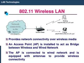
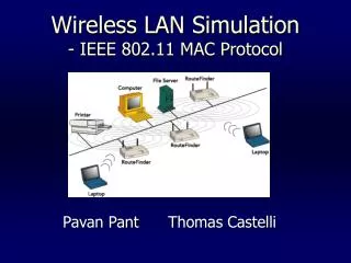
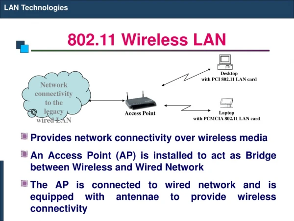
LAN Technologies. 802.11 Wireless LAN. Provides network connectivity over wireless media An Access Point (AP) is installed to act as Bridge between Wireless and Wired Network The AP is connected to wired network and is equipped with antennae to provide wireless connectivity. Desktop

802.11 Wireless LAN
E N D
Presentation Transcript
LAN Technologies 802.11 Wireless LAN • Provides network connectivity over wireless media • An Access Point (AP) is installed to act as Bridge between Wireless and Wired Network • The AP is connected to wired network and is equipped with antennae to provide wireless connectivity Desktop with PCI 802.11 LAN card Network connectivity to the legacy wired LAN Access Point Laptop with PCMCIA 802.11 LAN card
LAN Technologies 802.11 Wireless LAN • Range ( Distance between Access Point and WLAN client) depends on structural hindrances and RF gain of the antenna at the Access Point • To service larger areas, multiple APs may be installed with a 20-30% overlap • A client is always associated with one AP and when the client moves closer to another AP, it associates with the new AP (Hand-Off) • Three flavors: • 802.11b • 802.11a • 802.11g
LAN Technologies Multiple Access with Collision Avoidance (MACA) • Before every data transmission • Sender sends a Request to Send (RTS) frame containing the length of the transmission • Receiver respond with a Clear to Send (CTS) frame • Sender sends data • Receiver sends an ACK; now another sender can send data • When sender doesn’t get a CTS back, it assumes collision other node in sender’s range other node in receiver’s range sender receiver RTS CTS data ACK
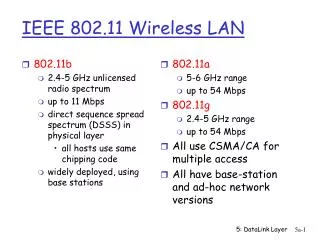
LAN Technologies WLAN : 802.11b • The most popular 802.11 standard currently in deployment. • Supports 1, 2, 5.5 and 11 Mbps data rates in the 2.4 GHz ISM (Industrial-Scientific-Medical) band
LAN Technologies WLAN : 802.11a • Operates in the 5 GHz UNII (Unlicensed National Information Infrastructure) band • Incompatible with devices operating in 2.4GHz • Supports Data rates up to 54 Mbps.
LAN Technologies WLAN : 802.11g • Supports data rates as high as 54 Mbps on the 2.4 GHz band • Provides backward compatibility with 802.11b equipment
Repeater, HUB, Bridge & Switch REPEATER, HUB, BRIDGE AND SWITCH
Repeater, Hub, Bridge & Switch Repeater • A repeater receives a signal, regenerates it, and passes it on. • It can regenerate and retime network signals at the bit level to allow them to travel a longer distance on the media. • It operates at Physical Layer of OSI • The Four Repeater Rule for 10-Mbps Ethernet should be used as a standard when extending LAN segments. • This rule states that no more than four repeaters can be used between hosts on a LAN. • This rule is used to limit latency added to frame travel by each repeater.
Repeater, Hub, Bridge & Switch Hub • Hubs are used to connect multiple nodes to a single physical device, which connects to the network. • Hubs are actually multiport repeaters. • Using a hub changes the network topology from a linear bus, to a star. • With hubs, data arriving over the cables to a hub port is electrically repeated on all the other ports connected to the same network segment, except for the port on which the data was sent.
Repeater, Hub, Bridge & Switch Bridge • Bridges are used to logically separate network segments within the same network. • They operate at the OSI data link layer (Layer 2) and are independent of higher-layer protocols. • The function of the bridge is to make intelligent decisions about whether or not to pass signals on to the next segment of a network. • When a bridge receives a frame on the network, the destination MAC address is looked up in the bridge table to determine whether to filter, flood, or copy the frame onto another segment • Broadcast Packets are forwarded
Repeater, Hub, Bridge & Switch Switch • Switches are Multiport Bridges. • Switches provide a unique network segment on each port, thereby separating collision domains. • Today, network designers are replacing hubs in their wiring closets with switches to increase their network performance and bandwidth while protecting their existing wiring investments. • Like bridges, switches learn certain information about the data packets that are received from various computers on the network. • Switches use this information to build forwarding tables to determine the destination of data being sent by one computer to another computer on the network.
Repeater, Hub, Bridge & Switch Switches: Dedicated Access A • Hosts have direct connection to switch • Full Duplex: No collisions • Switching: A-to-A’ and B-to-B’ simultaneously, no collisions • Switches can be cascaded to expand the network C’ B switch C B’ A’