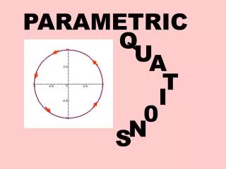
Parametric Sketching
Parametric Sketching. Motivation. Solid primitives not typically supported in parametric modelers must create a 2D profile, then sweep. Feature Creation Procedure. Choose sketch plane, either a: Default work plane Planar face of existing feature Work plane Rough sketch

Parametric Sketching
E N D
Presentation Transcript
Motivation Solid primitives not typically supported in parametric modelers must create a 2D profile, then sweep
Feature Creation Procedure • Choose sketch plane, either a: • Default work plane • Planar face of existing feature • Work plane • Rough sketch • Some geometric constraints applied • Add/delete geometric constraints • Parametric dimensioning • Feature creation • Repeat 1 - 5
Construction Geometry • Geometry created as part of the parametric modeling process that does not represent actual part geometry. Includes: • Work planes • Work axes • Work points • Construction geometry appears in feature tree
Default Construction Geometry: Inventor • Work planes – mutually perpendicular • YZ • XZ • XY • Work Axes • X (red) • Y (green) • Z (blue) • Work Point • Origin of WCS
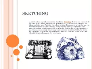
Rough Sketch • Parametric sketching imitates actual sketching process rough, approximate
Sketch Plane Views View normal to sketch plane Isometric View
Geometric Constraints • Typical constraints include: vertical, horizontal, collinear, concentric, tangent, etc. • Inventor constraints
Display Geometric Constraints • Software includes option to show constraints
Add/Delete Constraints • User can manually (explicitly) add constraints concentric tangent equal
Parametric Dimensions • Add parametric dimensions to fully constrain profile • Each parametric dimension has two components: • Numerical value • Name Fully Constrained Sketch
Parametric Dimensions - 2 • Default parameter names (e.g., d0) can be changed • Equations can be used to generate parameter value
Under and Over-constrained Sketches Under-constrained Angle not necessary Vertical position of hole not specified Over-constrained