Ultrasonic Testing
Ultrasonic Testing . By: Chris Wu CEE 398 3/5/04. Introduction . High-frequency sound waves are sent out at a material to find material changes A pulser produces an electrical pulse that causes a piezoelectric transducer to send out a sound wave


Ultrasonic Testing
E N D
Presentation Transcript
Ultrasonic Testing By: Chris Wu CEE 398 3/5/04
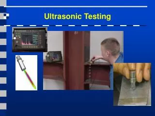
Introduction • High-frequency sound waves are sent out at a material to find material changes • A pulser produces an electrical pulse that causes a piezoelectric transducer to send out a sound wave • Reflected waves are transformed back into electrical signals by the transducer and analyzed • Its main applications are in thickness gauging and flaw detection
Background • Originated from sonar technology, which was developed just before World War II • Sonar uses technique of bouncing echoes off of submerged objects to detect them • Ultrasonics, a form of nondestructive testing, was applied to “safe life” design, which ensures that structures don’t develop macroscopic defects during its life, and any detection led to its removal
Background (cont’d) • In the early 1970’s, ultrasonic testing had made large strides and could detect extremely small defects or discontinuities in metals • An unforeseen downside was that many manufacturers were now discarding more metal parts that were deemed satisfactory earlier • This in turn led to fracture mechanics, which allowed the determination of whether “a crack of a given size would fail under a certain load if the fracture toughness were known (ndt-ed.org).”
Background (cont’d) • Fracture mechanics allowed for the concept of fail safe design, which stated that structures could have defects as long as they would not grow to cause failure. • Over the past few years, ultrasonic testing has become more popular due to advances in both computer and information technology
Theory and Technique • High frequency sound energy is used to find such things as material flaws and dimensional measurement • Items needed to run an ultrasonic test: • Pulser/receiver unit • Piezoelectric transducer • Display devices
The Role of Each Device • A pulser/receiver creates a high voltage electrical pulse, which is sent throught the material in the form of propagating sound waves by the transducer • Any discontinuity or flaw in the material will cause some energy to reflect back • The reflected waves are converted into an electrical signal by the transducer and amplified by the receiver for signal processing
The Role of Each Device (cont’d) • The amplified electrical signal is then displayed on a screen • The reflected signal strength is often displayed vs. time b/w signal generation and echo reception • D= vt/2 for normal beam inspection of discontinuities, different for angle beams • This can lead to info on the flaw’s size, location, and orientation among other things
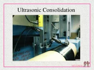
Picture Gallery Transducer Test Specimen Pulser/Receiver Display Device
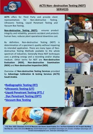
Pros • Advantages • Sensitive to both surface and subsurface discontinuities • Penetration depth is better than other NDT methods • With pulse-echo, access to only one side is needed • Highly accurate in regards to reflector size, shape, and location • Minimal part preparation
Cons • Disadvantages • Surface must be accessible to transmit ultrasound • More training required relative to other methods • Coupling medium is normally required to promote transfer of sound • Has difficulty inspecting rough, small, or irregularly shaped objects • Linear defects parallel to sound beam may go undetected
Piezoelectric Transducers • PT’s contain polarized material • When electric charge is applied, dipoles are induced and dimensions change • If a force is placed on the material, it will change dimensions and create an electric field
The Piezoelectric Effect Crystal material at rest: No forces applied, so net current flow is 0 Crystal + - + - + - Current Meter = 0 Charges cancel each other, so no current flow + - + - + -
The Piezoelectric Effect Crystal Crystal material with forces applied in direction of arrows……….. - - - - - Force Current Meter deflects in + direction + + + + + Due to properties of symmetry, charges are net + on one side & net - on the opposite side: crystal gets thinner and longer
The Piezoelectric Effect Changing the direction of the applied force……….. Crystal + + + + Force Current Meter deflects in - direction - - - - - …. Changes the direction of current flow, and the crystal gets shorter and fatter.
The electromechanical effect When the switch is closed, and you apply the exact amount of power to get the same current that resulted when you squeezed the crystal, the crystal should deform by the same amount!! Crystal + + + + + side power source (battery) - - - - - - side …. and, the crystal should get shorter and fatter.
Contact Direct contact w/ specimen Rugged casing and plates Uses coupling material to remove air gaps Immersion Non-contact Operates in liquid Transducer types
References • www.ndt-ed.org • www.ndt.net • www.ndtsupply.com • www.qnetworld.com