Download
1 / 6
0 likes | 24 Vues
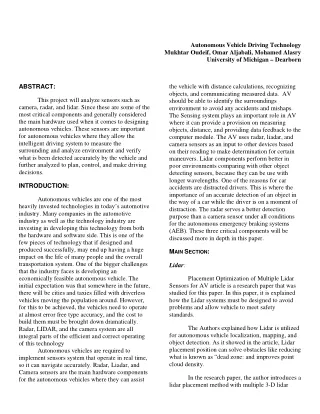
This project will analyze sensors such as camera, radar, and lidar. Since these are some of the most critical components and generally considered the main hardware used when it comes to designing autonomous vehicles. These sensors are important for autonomous vehicles where they allow the intelligent driving system to measure the surrounding and analyze environment and verify what is been detected accurately by the vehicle and further analyzed to plan, control, and make driving decisions.

E N D
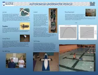
Autonomous Vehicle Driving Technology Mukhtar Oudeif, Omar Aljabali, Mohamed Alasry University of Michigan – Dearborn ABSTRACT: the vehicle with distance calculations, recognizing objects, and communicating measured data. AV should be able to identify the surroundings environment to avoid any accidents and mishaps. The Sensing system plays an important role in AV where it can provide a provision on measuring objects, distance, and providing data feedback to the computer module. The AV uses radar, liadar, and camera sensors as an input to other devices based on their reading to make determination for certain maneuvers. Lidar components perform better in poor environments comparing with other object detecting sensors, because they can be use with longer wavelengths. One of the reasons for car accidents are distracted drivers. This is where the importance of an accurate detection of an object in the way of a car while the driver is on a moment of distraction. The radar serves a better detection purpose than a camera sensor under all conditions for the autonomous emergency braking systems (AEB). These three critical components will be discussed more in depth in this paper. This project will analyze sensors such as camera, radar, and lidar. Since these are some of the most critical components and generally considered the main hardware used when it comes to designing autonomous vehicles. These sensors are important for autonomous vehicles where they allow the intelligent driving system to measure the surrounding and analyze environment and verify what is been detected accurately by the vehicle and further analyzed to plan, control, and make driving decisions. INTRODUCTION: Autonomous vehicles are one of the most heavily invested technologies in today’s automotive industry. Many companies in the automotive industry as well as the technology industry are investing in developing this technology from both the hardware and software side. This is one of the few pieces of technology that if designed and produced successfully, may end up having a huge impact on the life of many people and the overall transportation system. One of the bigger challenges that the industry faces is developing an economically feasible autonomous vehicle. The initial expectation was that somewhere in the future, there will be cities and taxies filled with driverless vehicles moving the population around. However, for this to be achieved, the vehicles need to operate at almost error free type accuracy, and the cost to build them must be brought down dramatically. Radar, LIDAR, and the camera system are all integral parts of the efficient and correct operating of this technology Autonomous vehicles are required to implement sensors system that operate in real time, so it can navigate accurately. Radar, Liadar, and Camera sensors are the main hardware components for the autonomous vehicles where they can assist MAIN SECTION: Lidar: Placement Optimization of Multiple Lidar Sensors for AV article is a research paper that was studied for this paper. In this paper, it is explained how the Lidar systems must be designed to avoid problems and allow vehicle to meet safety standards. The Authors explained how Lidar is utilized for autonomous vehicle localization, mapping, and object detection. As it showed in the article, Lidar placement position can solve obstacles like reducing what is known as “dead zone: and improves point cloud density. In the research paper, the author introduces a lidar placement method with multiple 3-D lidar
Page 2 of 6 operation system that can resolve AV Lidar obstacles. Three Lidar sensors are placed in front and rear side of the vehicle to cover all zones. Each lidar has its own coverage zones where vertical and horizontal angular resolution are calculated. In figure 1, a Vertical and Horizontal Angular of Lidar is shown. Lidar spoofing attack detection in autonomous vehicles article explain in detail how Lidar sensors may face a spoofing attack via laser satirizing. The authors explained how Lidar is unprotected against laser satirizing attacks, which can result in hazardous actions, for example, applying or not applying the brakes. As it showed in the article a proposed model utilizing machine learning can detect Lidar spoofing attacks. Figure 3 is showing the general steps of the proposed model. Figure 1: Vertical and Horizontal Angular of Lidar The coverage overlaps between all Lidars showed an increase of number of points cloud density since they are combined. The Lidar grid value was calculated mathematically using a formula based on the Lidar positions. In addition, a genetic algorithm was developed for the Lidar placement. As a result, position of Lidars proved the improvement in performance and robustness of the Lidar solution. The below figure shows the placement of the three lidars. Figure 3: The general steps of the proposed model In the article, the proposed model is relying on a decision tree to detect Lidar spoofing attack. The authors system architecture was split into two phases: training phase and testing phase. 60% of the data were used as training data based on autonomous vehicle, Lidar scanner, decision tree, then accuracy training threshold and 40% as test data based on the decision tree and results. The dataset selection depended on an AV dataset gathered over a long time at the University of Michigan. The dataset comprises omnidirectional symbolism, planar Lidar data, 3D Lidar data, GPS data, and data from proprioceptive sensors for odometry. The decision trees are very convincing methodology for determining the unique conditions. Characterization and relapse issues are utilized for decision trees. Based on the machine learning method and algorithm used in this experiment to detect spoofing attacks, the decision trees approach had a mean absolute error of 3.0068, root mean Figure 2: (a) Placement of three lidars: #1, #2, #3. (b) Coverage of each lidar (top view). (c) Coverage- overlapped zones: #1-#2, #2-#3, #1-#3 (top view)
Page 3 of 6 squared of 0.0002 and mean squared error of 6.7637. The experiment results showed 93.24 accuracy of detection. radar waves get reflected to a pc to interpret the detected object whether it is a pedestrian or a vehicle. Figure 4: The compares approach with the results of previous work Figure 4 compares between the approach with the results of previous work In every technical paper reviewed, the authors introduced various techniques that they believe could assist some of these difficult issues related to LIDAR and offer the autonomous technology a robust and accurate vehicle position detection method. Per the findings of the papers, their methods seemed to yield very successful results and may be adopted for use with the operating of autonomous vehicles during the development phase. Figure5: Architecture of the proposed PVR system The radar received signal power which is calculated using an equation base on the received signal power, transmitted signal electric power, transmitting antenna gain, receiving antenna gain, and a radar cross section. The RCS of the object is calculated using the same equation. As the object distance varies, this results in a change to the transmitting antenna and receiving antenna gain. The standard deviation of width of objects is calculated by plotting the expected normal distribution of azimuth angle of an object on a distribution curve scaled zero to plus and minus 3 sigma. The standard deviation of the azimuth angle to an object from host vehicle is calibrated base on upper and lower bound of width of pedestrian and vehicle. Radar: A transmitter, antenna, receiver, signal processing and a display screen are the 5 main components of radar. Detection of an abject and providing an accurate data is critical radar function for timing on a moving vehicle. In some cases where the obstacle is large or small lateral, the binaural radar model is a good way to differentiate between a crossing pedestrian and close trajectories. Two papers were also reviewed related to Radar technology and how it relates to autonomous vehicles. In the first paper reviewed, the use of Radar sensor in the autonomous emergency braking was studied. The paper covered vehicle and pedestrian recognition (PVR) algorithm (PVR). The PVR system architecture used in this paper consist of a MMWR (radar system unit) mounted in front of a vehicle, RCS calculation module, computer, information module and an object, vehicle, and pedestrian. The Radar targets an object where the Figure 6: The standard deviation of the azimuth angle to an object from host vehicle. The results shows that the width of pedestrian is close to 0.4m, 0.7m, and 1.1m for α=1, 2, and 3, respectively. The best results were collected for the azimuth angles when using α=2.The experimental results for the vehicle recognition calculated at azimuth angle of 0 degree of the vehicle is in front
Page 4 of 6 of the host vehicle. The results shows that the width of vehicle is about 0.4m, 0.7m, and 1.1m for α=1, 2, and 3, respectively. The best results were collected for the azimuth angles when using α=3. applied in a real road situation for the fusion of the Radar and camera systems. The experimental data collected from the road shows that the camera is excellent at detecting objects but not as good for the velocity measurement. On the contrary, the data collected from the road shows that the radar is excellent at the velocity measurement but not as good for detecting objects. Therefore, the fusion of camera and radar system gives a dependable object tracking system more accurately. In the second paper reviewed, the use of data fusion for multiple vehicles tracking systems using a radar and camara systems in autonomous driving. The author explains the estimation algorithm, data processing, and validation of the data on the roads. The trajectory of the tracking vehicles is given by the combined data of the radar and the smart camara. The Data from both, the radar and the camara gets combined by the algorithm as a non- synchronized data via models that are used to predict the state of an object at a required time. An environment is a static or a moving object. Where the reflected signal is received either by the radar or the smart camera. From the Rada, the clustered signal transfers to a track list then to a data association. Then the radar system applies one of the more sophisticated filter’s referred to in industry as a “Kalman Filter” to the signal to help remove noise. After being filtered, the signal goes through a radar track list then to the data fused track list to be combined with the camera data. Finally, the track management published the track. Figure7: Ego car with Radar measurement The road experimental data established the validation of the system structure. The camera is excellent at detecting objects but not as good for the velocity measurement. while the radar is excellent at the velocity measurement but not as good as the camera for detecting objects. The radar gives out more feedback and reflections counting clutters. A reliable tracking system can be achieved using the combined radar and camera systems. This shows the integration of both is essential for successful operation of an autonomous vehicle. Starting with the Radar’s filter used for detected signal. The Radar system can directly calculate the radial velocity of the dynamic object when moving toward and away from the sensor. The coordinate system of the ego vehicle has the x axis points in the direction of movement and y axis points to the left. The Radar directly calculate the object range, bearing and range rate ¬. The radical distance from the origin of the sensor to the object is called the range. The angle between the range and the x direction is the bearing and the range rate also known as radial velocity is the velocity along this ray. The Kalman filter estimates the state of the object in two step processes. The object tracking is done by basic motion model with constant velocity. The smart camara system use a Kalman filter detection base the same at the radar detection system. The camara uses a cartesian coordinates like the radar system. The need to track different objects at the same time requires a clustering algorithm to do that. The tracking algorithm is Camera: The camera being part of the vision system in an autonomous vehicle is very critical. This is what collects a lot of the data that the vehicle uses in its algorithms to determine speed, stopping, turning, and obstacle recognition along with many other vehicle decisions. Effective and quick operation is foundational if an autonomous vehicle to be successful. This can be done by adding many expensive components like lidar’s or by using various camera set ups. An article that has been read and analyzed used what is referred to as “Variable Focus Camera.” Since these cameras provide very critical sensor data that is used for calculations and
Page 5 of 6 decision making, their accuracy is essential for Autonomous Vehicles. This is a camera that is single, and the view angle varies. With the ability to update the view angle, this allows the camera to consider spaces that are normally recognized by more expensive hardware such as lidar’s. This helps provide a basis for a more efficient and cheaper design in terms of hardware as less sensors that cost more may be able to be used. It also potentially means less weight on a vehicle which is also cost efficient for the company producing the vehicle and the customer operating the vehicle. Of course, there are still concerns with external factors such as bad weather elements impeding the functionality of the camera, but this can also be addressed with software and slight hardware additions to keep the lens clean. The camera used here allows a wide angle in terms of the view. The camera ability to change angles, allows it to grab a much wider view when functioning. This in a way now can start doing some of the job that more expensive hardware such as LIDAR does. If this camera is able to continuously be improved or maybe more camera’s are added, then the thought is that LIDAR’s and different radar’s that carry a very heavy price tag can be reduced on autonomous vehicle. This is a topic that is greatly being researched as some of these technologies make the development of autonomous vehicles economically unfeasible. It can also cause the vehicle to be lighter which impacts material cost as well as fuel efficiency of the vehicle. The article did mention the negative impact that rain and mud had on the performance of the camera which is something that will need to be addressed if this is to be adopted industry wide as a serious alternative to heavy use of more expensive hardware like LIDAR. The obtained results were within what could be considered safe operation of an autonomous vehicle. This shows as an early step that this type of camera can be used and can help limit some of the need to add some of the other more expensive sensors. Which in my opinion, makes the development of autonomous vehicles more likely. The next figure is a drawing of a schematic related to the variable focus camera and its vision. Another research paper was reviewed where the a model referred to as “RSS” was used to analyze these camera’s and their related operation. The “RSS” models from mathematical point of view different rules that apply to various variables that impact the safe operation of a vehicle like distance, responsiveness to various situations and other items. It also took into account many of the causes for almost all vehicle accidents in America when deriving this model. One shortcoming of this model is that it works under the assumptions that vehicles can communicate with each other and thus make efficient and safe decisions based on what the other vehicle is telling it. The math specifics behind this model is very complex and will not be discussed in depth. However, some of the more critical variables were maximum acceleration, minimum braking, and maximum braking. Please see the article for more input and depth. The model did show that the vehicle using this camera operated safely and passed expectations. However, it also mentioned that the model was developed and operated under the assumption of more ideal conditions during testing. Rain and other harsh conditions were not tested as the expectations of a negative impact was also considered. Therefore, more testing and adjusting to more real conditions is needed. Currently, no company has Figure8: Variable focus camera view schematic
Page 6 of 6 full autonomous vehicles out to market. There are vehicles on the road that can operation by themselves, but they are not at the point where they can be mass produced for many reasons. One being economic feasibility and this camera may be a potential solution to that. The next figure shows the coverage provided from this camera, a radar and LIDAR from a lateral perspective. They all have their advantages and disadvantages in terms of coverage. safety and cost as both are essential drivers to help bring these products to scale. As of yet, no company can claim to have a full autonomous vehicle on the market although development and testing is still ongoing. R REFERENCES EFERENCES: : [1] Tae-Hyeong Kim and Tae-Hyoung Park. " Placement Optimization of Multiple Lidar Sensors for Autonomous Vehicles." IEEE (2020). Web. [2] Khattab Alheeti, Abdulkareem Alzahrani and Duaa Aldosary. " LiDAR Spoofing Attack Detection in Autonomous Vehicles." IEEE (2022). Web. [3] Li, F., Wu, Z., Zhu, Y., and Lu, K., "Radar and Smart Camera Based Data Fusion for Multiple Vehicle Autonomous Driving," SAE Technical Paper 2022-01-7019, https://doi.org/10.4271/2022-01-7019. [4] Wu, T., "Pedestrian and Vehicle Recognition Based on Radar for Autonomous Emergency Braking," SAE Technical Paper 2017-01- 1405, 2017, https://doi.org/10.4271/2017- 01-1405. [5] Nick Goberville, Mohammad El-Yabroudi, Mark Omwanas, Johan Rojas, Rick Meyer, Zachary Asher, and Ikhlas Abdel-Qader, " Analysis of LiDAR and Camera Data in Real-World Weather Conditions for Autonomous Vehicle Operations," Web. 3 April. 2020 [6] Krage, M., "Binaural Automobile Radar," SAE Technical Paper 750089, 1975, https://doi.org/10.4271/750089. [7] Min Joong Kim, Tong Hyun Kim, Sung Hun Yu, and Young Min Kim1" Safety Verification of RSS ModelBased Variable Focus Function Camera for Autonomous Vehicle," Web. 14 Feb. 2022 Tracking System in 2022, Figure9: Converge provided by the different sensors C CONCLUSION ONCLUSION: : Autonomous vehicle development is the focus in the automotive industry. With the utilization of sensors such as Radar, Lidar, and Camera autonomous vehicle keep on improving as they go through the testing. Improving these components will allows the automotive business to achieve its goal and provide a product that are reliable and safe. Continuous focus is placed on