Download
1 / 20
690 likes | 3.47k Vues
Wien-Bridge Oscillator Circuits. By Darren De Ronde May 15, 2002. Why Look At the Wien-Bridge?. It generates an oscillatory output signal without having any input source. Basics About the Wien-Bridge.

E N D
Wien-Bridge Oscillator Circuits By Darren De Ronde May 15, 2002
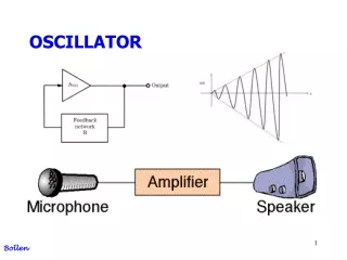
Why Look At the Wien-Bridge? • It generates an oscillatory output signal without having any input source
Basics About the Wien-Bridge • Uses two RC networks connected to the positive terminal to form a frequency selective feedback network • Causes Oscillations to Occur
Basics About the Wien-Bridge • Amplifies the signal with the two negative feedback resistors
Z1 Z2 Modification to Circuit
Z1 Z2 Analysis • The loop gain can be found by doing a voltage division
Z1 Z2 Analysis • The two RC Networks must have equal resistors and capacitors
Analysis Need to find the Gain over the whole Circuit: Vo/Vs Solve G equation for V1 and substitute in for above equ.
Analysis We now have an equation for the overall circuit gain Simplifying and substituting jw for s
Analysis If G = 3, oscillations occur If G < 3, oscillations attenuate If G > 3, oscillation amplify
G = 3 G = 2.9 G = 3.05
Ideal vs. Non-Ideal Op-Amp • Red is the ideal op-amp. • Green is the 741 op-amp.
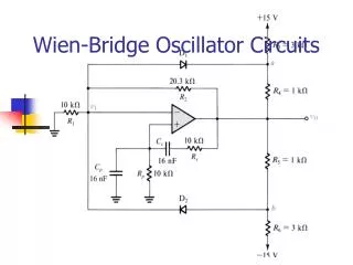
Making the Oscillations Steady • Add a diode network to keep circuit around G = 3 • If G = 3, diodes are off
Making the Oscillations Steady • When output voltage is positive, D1 turns on and R9 is switched in parallel causing G to drop
Making the Oscillations Steady • When output voltage is negative, D2 turns on and R9 is switched in parallel causing G to drop
Results of Diode Network • With the use of diodes, the non-ideal op-amp can produce steady oscillations.
Frequency Analysis • By changing the resistor and capacitor values in the positive feedback network, the output frequency can be changed.
Frequency Analysis Fast Fourier Transform of Simulation
Frequency Analysis • Due to limitations of the op-amp, frequencies above 1MHz are unachievable.
Conclusions • No Input Signal yet Produces Output Oscillations • Can Output a Large Range of Frequencies • With Proper Configuration, Oscillations can go on indefinitely