Download
1 / 35
370 likes | 537 Vues
Dive into the world of crystal oscillators, from Colpitts to Hartley, and discover their significance in radio circuits, microprocessors, and more. Learn how crystal oscillators work and why they are preferred for stability and efficiency in electronic devices.

E N D
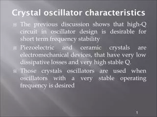
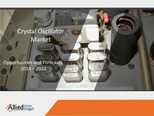
The crystal oscillator is an oscillator in which the resonance circuit is a crystallization of quartz rather than coil and capacitor. It is the best type of oscillators, the lowest energy consumption and the most stable in frequency . So they are often used in radio circuits and communication equipment circuits • In computer circuits and microprocessor circuits
The most characteristic of this type of oscillators is the frequency stability. It is much better than the LC oscillator. What distinguishes these oscillators is the presence of quartz crystal (quartz crystal) With a specific pulse in its circuits.
The crystallization of the quartz used in this type of oscillators is characterized by appearance Distribute the voltage between the opposite ends when applying mechanical forces between the two parties Others, called this phenomenon (piezoelectric effect), and also when there is Constant voltage difference between two opposite sides of this crystalline shape Any mechanical changes occur to it stretch or shrink.
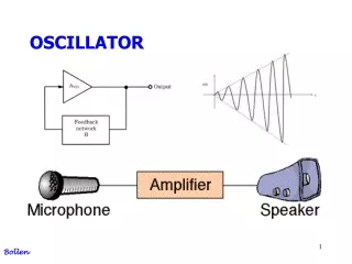
A phase-shift oscillator is a linear electronic oscillator circuit that produces a sine wave output. It consists of an inverting amplifier element such as a transistor or op amp with its output fed back to its input through a phase-shift network consisting of resistors and capacitors in a ladder network. The feedback network 'shifts' the phase of the amplifier output by 180 degrees at the oscillation frequency to give positive feedback.
Hartley oscillator • The Hartley oscillator is an electronic oscillator circuit in which the oscillation frequency is determined by a tuned circuit consisting of capacitors and inductors, that is, an LC oscillator. The circuit was invented in 1915 by American engineer Ralph Hartley. The distinguishing feature of the Hartley oscillator is that the tuned circuit consists of a single capacitor in parallel with two inductors in series (or a single tapped inductor), and the feedback signal needed for oscillation is taken from the center connection of the two inductors.
Clopitts oscillator • A Colpitts • oscillator, invented in 1918 by American engineer Edwin H. Colpitts,[1] is one of a number of designs for LC oscillators, electronic oscillators that use a combination of inductors (L) and capacitors (C) to produce an oscillation at a certain frequency. The distinguishing feature of the Colpitts oscillator is that the feedback for the active device is taken from a voltage divider made of two capacitors in series across the inductor
An electronic oscillator is an electronic circuit that produces a periodic, oscillating electronic signal, often a sine wave or a square wave. Oscillators convert direct current (DC) from a power supply to an alternating current (AC) signal. They are widely used in many electronic devices. Common examples of signals generated by oscillators include signals broadcast by radio and television transmitters, clock signals that regulate computers and quartz clocks, and the sounds produced by electronic beepers and video games
Oscillators are often characterized by the frequency of their output signal: • A low-frequency oscillator (LFO) is an electronic oscillator that generates a frequency below approximately 20 Hz. This term is typically used in the field of audio synthesizers, to distinguish it from an audio frequency oscillator. • An audio oscillator produces frequencies in the audio range, about 16 Hz to 20 kHz.] • An RF oscillator produces signals in the radio frequency (RF) range of about 100 kHz to 100 GHz
A crystal oscillator is an electronic oscillator circuit that uses the mechanical resonance of a vibrating crystal of piezoelectric material to create an electrical signal with a precise frequency.[ This frequency is commonly used to keep track of time, as in quartz wristwatches, to provide a stable clock signal for digitalintegrated circuits, and to stabilize frequencies for radio transmitters and receivers. The most common type of piezoelectric resonator used is the quartz crystal, so oscillator circuits incorporating them became known as crystal oscillators,[1] but other piezoelectric materials including polycrystalline ceramics are used in similar circuits.
A crystal oscillator, particularly one made of quartz crystal, works by being distorted by an electric field when voltage is applied to an electrode near or on the crystal. This property is known as electrostriction or inverse piezoelectricity. When the field is removed, the quartz - which oscillates in a precise frequency - generates an electric field as it returns to its previous shape, and this can generate a voltage. The result is that a quartz crystal behaves like an RLC circuit.
:Oscillators are classified by pulse output 1- Sound oscillator produces frequencies in the audio range from 16HZ to 20HZ. 2- the radio oscillator produces signals at the radio frequency from 100KHZ to 100GHZ. 3-A low frequency oscillator is an electronic oscillator that generates frequencies below 20HZ.
An oscillatory circuit produces electrical oscillations of a desired frequency. They are also known as tank circuits. • A simple tank circuit comprises of an inductor L and a capacitor C both of which together determine the oscillatory frequency of the circuit. • To understand the concept of oscillatory circuit, let us consider the following circuit. The capacitor in this circuit is already charged using a dc source. In this situation, the upper plate of the capacitor has excess of electrons whereas the lower plate has deficit of electrons. The capacitor holds some electrostatic energy and there is a voltage across the capacitor
When the switch S is closed, the capacitor discharges and the current flows through the inductor. Due to the inductive effect, the current builds up slowly towards a maximum value. Once the capacitor discharges completely, the magnetic field around the coil is maximum.
Once the capacitor is fully charged, it starts to discharge to build up a magnetic field around the coil, as shown in the following circuit diagram
1-used in communication systems where they are used as transmitter for signal of information and at receivers as local oscillators to select channels to be received • 2-used in filter circuits that select the electrical signals to be received from thousands of signals • 3-used in medical equipment to generate electrical signals and some types of radiation • 4-also used in control systems to build small and high precision control equipment for different application such as factories and power plants