Download
1 / 39
490 likes | 1.14k Vues
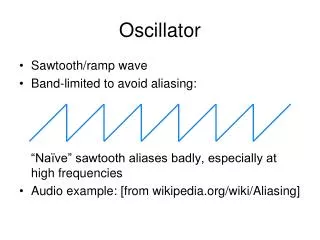
Crystal oscillator characteristics. The previous discussion shows that high-Q circuit in oscillator design is desirable for short term frequency stability Piezoelectric and ceramic crystals are electromechanical devices, that have very low dissipative losses and very high stable Q.

E N D
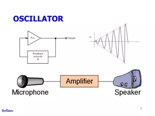
Crystal oscillator characteristics The previous discussion shows that high-Q circuit in oscillator design is desirable for short term frequency stability Piezoelectric and ceramic crystals are electromechanical devices, that have very low dissipative losses and very high stable Q. Those crystals oscillators are used when oscillators with a very stable operating frequency is desired 1
Crystal oscillator equivalent circuit An equivalent circuit of the crystal oscillator contains several series resonant circuits as shown below The frequencies of these resonant elements are all approximate odd harmonics of the fundamental frequency f0 The higher resonant frequency region around any resonant are referred to as overtones of the fundamental frequency 2
Crystal oscillator equivalent circuit In a narrow frequency region around any resonant frequency fi , the equivalent circuit can be simplified as shown 4
Crystal oscillator equivalent circuit If r is zero then the input impedance of the crystal will be The impedance Z(jω) will be zero when the inductor L1 and C1 are in resonance The frequency of oscillation which is referred as the series resonant frequency which is given by 5
Crystal oscillator equivalent circuit The crystal impedance will be infinite at the frequency fa is referred as the antiresonant frequency The effect of a non zero r on the circuit can be calculated from the equation 6
Crystal oscillator equivalent circuit The series and antiresonant frequencies will be very close to those calculated for the case when r is zero The only difference when r is not zero is that the Q value will be less The effect of r1on the antiresonant behavior can be evaluated by making a series to parallel transformation 7
Crystal oscillator equivalent circuit The equivalent parallel impedances are given by Where At antiresonance, the equivalent parallel reactance must be equal to the reactance of the shunt capacitor and 8
Crystal oscillator equivalent circuit At fa the series reactance Xs is large, so that Qs>>1, therefore XCO≈Xs and 9
Crystal oscillator equivalent circuit Circuits containing crystals are frequently designed so that the frequency range of interest is between the series resonant and antiresonant frequencies of the crystal The ratio of the antiresonant to the series resonant frequency is given by 10
Crystal oscillator equivalent circuit The shunt capacitance CO normally is much greater than C1 so that the Taylor series expansion reduces to Typical values of k lie between 250 and 300 The crystal antiresonant frequency is higher than the its series resonant frequency 11
Crystal oscillator example Example: a given crystal oscillator has C0=3.2 pF and C1=8 fF, determine the series resonant frequency if the crystal antiresonant frequency is 1 MHz Solution: the series resonant frequency can be found from the following relation 12
Crystal oscillator impedance The impedance of the crystal oscillator can be rewritten as It is seen from this equation that the impedance is inductive for the frequency range The impedance will be capacitive for other frequency ranges as shown in the next figure 13
Parallel mode crystal oscillator Crystals are used as either parallel or series resonant circuit in oscillators If the crystal is used in the antiresonant mode, the circuit is referred as a parallel mode crystal oscillator In parallel mode the crystal actually serves as an inductor If the crystal is used as a series resonant circuit, then the circuit is referred as a series mode crystal oscillator 15
Parallel mode crystal oscillator The oscillator design procedure is the same design procedure for non crystal except that the biasing network can be different The reason for the difference came from the fact that crystals block DC voltages 16
Parallel mode crystal oscillator example Example: Design 20-MHz Colpitts parallel-mode crystal controlled oscillator Solution: The oscillator can be converted to a crystal-controlled oscillator simply by replacing the inductor with a parallel-mode crystal antiresonant at 20 MHz If the crystal load capacitance is 32 pF, then the series combination of C1 and C2 must be 32 pF. This could be satisfied by using C1=C2=64 pF 17
Capacitors in parallel with parallel mode crystal Oscillator In some applications such as voltage controlled oscillator it is necessary to adjust the frequency of oscillation This can be achieved by adding an external loading capacitor (CL) in parallel with the crystal as shown in the figure 19
Capacitors in parallel with parallel mode crystal Oscillator The resulting antiresonant frequency is given by By increasing CL, fa can be decreased until fa≈fs The frequency range given by is referred as the pulling range of the crystal The above equation shows that the parallel antiresonant frequency can be pulled down to the series resonant frequency But this pulling will results in poor performance for parallel-mode oscillators, since Q is simultaneously reduced 20
Capacitors in parallel with parallel mode crystal Oscillator 21
Series-Mode Crystal Oscillator Crystal oscillator can be used in series mode in the Clapp-Gouriet configuration shown below At the resonant frequency the crystal impedance is zero and it is very large at other frequencies 22
Series-Mode Crystal Oscillator At frequencies other than its series resonant frequency, the crystal impedance is large enough to prevent current from being fed back to the emitter. The tank circuit is designed to be antiresonant at the series resonant frequency of the crystal The small signal equivalent circuit is shown below 23
Series-Mode Crystal Oscillator The voltage fed back is given by Provided that which will be the case near the series resonant frequency. The output voltage is given by , where ZL is the load impedance given by The open loop gain can be given by 24
Series-Mode Crystal Oscillator The stability factor of a series mode crystal is given by Where QL is the quality factor of the parallel tuned circuit which is less than that of the crystal Qx In practical cases QL<<Qx and the stability factor can by approximated by 25
Series-Mode Crystal Oscillator Another series mode crystal is shown in this figure This circuit is referred to as the impedance-inverting Pierce oscillator 26
Series-Mode Crystal Oscillator A simple test to determine whether a crystal operates in the series or parallel mode in a circuit is to replace the crystal by a short circuit If the circuit will not oscillate with crystal shorted then the oscillator will be a parallel mode oscillator Otherwise it is a series mode oscillator 27
Capacitors in series with the crystal The frequency of series mode crystal can be adjusted by adding a capacitor in series with the crystal The series capacitance will alter the series frequency but not the antiresonant frequency 28
Capacitors in series with the crystal The added series capacitor will result in a new equivalent circuit as shown below Where is given by n is given by 29
Capacitors in series with the crystal The anti resonant frequency is given by The series resonant frequency is given by 30
Capacitors in series with the crystal The resulting variation in the input impedance of the crystal and the series added capacitor is shown below 31
Voltage controlled Oscillators Voltage controlled oscillators (VCO) can be built around any of the previous oscillator circuits by inserting a varactor diode with the oscillator circuits Examples of VCOs are as shown 32
Voltage controlled Oscillators • If the VCO is crystal controlled, the oscillator is referred to as voltage controlled oscillator (VCXO) 33
Voltage controlled Oscillators • A frequently used VCO is shown below • The modulating voltage fm in the figure of the previous slide changes the varactor voltage and therefore the diode capacitance hence the oscillation frequency 34
Voltage controlled Oscillators • A main difficulty in VCO design is to achieve a linear voltage-frequency transfer characteristics • The idealized voltage-frequency characteristics is shown below 35
Relaxation Oscillator The relaxation oscillator consists of an active device plus resistor and a capacitor The resistor and the capacitor act as a timing control for the oscillator A simplified version of the relaxation oscillator is shown below 36
Relaxation Oscillator The capacitor is charged by a constant current source When the capacitor voltage reaches a certain level, it causes the Schmitt trigger to fires and causes the current source to switch direction When the current direction in the constant current source is reversed the capacitor start to discharge When the capacitor voltage drop to a certain a mount the process repeats itself again 37
Relaxation Oscillator Examples of the relaxation oscillator are the 555 timer and the multivibrator oscillators The multivibrator is illustrated in the figure shown 38
Relaxation Oscillator The advantageous of relaxation oscillators over the LC oscillators are Relaxation oscillators can be linearly controlled over much broader frequency range Relaxation oscillators can operate at a very low power level The disadvantageou relaxation oscillator is that there frequency of operation is low compared to LC or crystal oscillators 39