Download
1 / 16
160 likes | 367 Vues
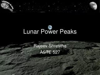
A Solar Electric Propulsion Mission with Lunar Power Beaming. Henry W. Brandhorst, Jr. , Julie A. Rodiek and Michael S. Crumpler Space Research Institute, Auburn University Mark J. O’Neill ENTECH, Inc. June 4, 2007. Outline. Introduction Getting to the moon Lunar Orbit Equatorial Orbit

E N D
A Solar Electric Propulsion Mission with Lunar Power Beaming Henry W. Brandhorst, Jr., Julie A. Rodiek and Michael S. Crumpler Space Research Institute, Auburn University Mark J. O’Neill ENTECH, Inc. June 4, 2007
Outline • Introduction • Getting to the moon • Lunar Orbit • Equatorial Orbit • Orbital analysis • Power delivery • Polar Orbit • Orbital analysis • Power delivery • Summary and Conclusions
Rationale • NASA’s Vision for Space Exploration to return to the moon • Lunar south pole desired location • Up to 70% sunlight per year • Other locations being driven by science • Equatorial and high latitude locations • Energy storage for the lunar night is massive • Solar array/RFC system – 20 kWe • Weight ~6 MT with cryogenic storage • Can power beaming reduce the mass of night time storage? • Orbital options to provide power to locations within ±45º of the equator • Molniya-type orbits for polar -90 to 45º S (or +90 to 45º N) • Two year orbital analysis
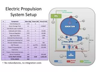
Getting to the Moon • Solar electric propulsion mission • ~4343 kg spacecraft • 1400 kg Xe propellant • Hall thrusters – 10 to 50 kW (3) • 100 kW Stretched Lens Solar Array • 300 W/kg, 300 W/m2,TJ cells • No detailed design of spacecraft • Spiral out through Van Allen belts • 500 km initial orbit, 28º inclination • 89 day trip time, plane change at moon • Compared to 272 day trip time from previous SEP space tug analysis • Radiation dose calculated with SPENVIS • Provides solar array degradation Selected shielding
Lunar Orbit – Single Spacecraft • Wide range of elliptical equatorial orbits examined • Chose 500 x 30,000 km orbit • Ran STK 7.1 for arbitrary 2-year period • July 1, 2008 to June 30, 2010 • Determined when surface sites between ±45º were in view of the satellite • AND the satellite was in sunlight • Times without satellite coverage were up to 164 hours (6.83 days) • Offers no major reduction in energy storage mass
Lunar Orbit – Two Spacecraft(500 x 30,000 km equatorial orbits) 2nd satellite access times with orbital location Equatorial satellite orbits about the moon with beaming
Dual Satellite View Times • Adding second satellite had a major impact on view times • Adjusting orbital relationship between the satellites boosted view times • Satellite 2: 3870 hrs access • Power beaming times increased significantly: • Only 8 periods of 84 hrs (3.5 days) with no access • Rest of the time it’s lower than 54 hrs (2.25 days) • Substantially reduces the mass of surface storage system
Overlapping Coverage • Because the satellites are in equatorial orbits, their view times often overlap • Provides an opportunity for substantial power increases • Beaming laser power to a planar GaAs (1-J) photovoltaic array on surface • Monochromatic laser beam cannot excite multiple junction solar cells • Can’t use tracking concentrator array to simultaneously view two satellites
Laser Power Beaming Laser beam incidence angles • Uses 850 nm diode pumped laser, 4 m2 area (2.26 m dia) beaming aperture • Aperture controls surface beam size • ~90 kW satellite power available • Laser beam incidence angles determined by satellite orbit • Surface array may track in the E-W axis when in sunlight • Laser intensity varies due to view angles and orbital elevation • Satellite near moon when beaming starts – high intensity • At 30,000 km, beam intensity drops to ~0.2 AM0 sunlight
Surface Solar Array/Laser Beam • Assuming 1-J GaAs cell surface solar array • Nominal 40 kW surface power • ~18% efficient GaAs cells • Temperature corrected • Size of laser beam on surface GaAs solar array determined • Less than total array area for maximum power delivery • Largest beam size is at 30,000 km distance • About 60% of GaAs surface solar array is covered
Lunar Power Produced by Laser • Chose 45º N site for calculation • Most difficult case • Calculated laser beam power from satellite • 50% conversion of orbital electricity into laser beam • Plus 12% mirror losses • Calculated laser power received by surface GaAs solar array • 45% conversion efficiency • 18 kW power delivered to site • Adequate for night time power needs • Storage for 64 hrs maximum • However, NASA’s interest is in a south polar location, so…
Polar Power Beaming Satellites • Two satellites in polar elliptical orbit • Offset by ~180º • 500 x 5,000 km orbit • ~7.5 hr orbital time • Apogee over the south pole • 850 nm laser beam • 1.5 m2 aperture (1.38 m dia) • Increases beam size on surface vs previous case • Uses 1-J GaAs tracking array on surface • Can track only one satellite • Or can use fixed array • Reduces surface power
Satellite Parameters – 8/23-24/08(500 x 5,000 km Polar Orbit)
Access Times for Polar Orbits • Polar orbits give excellent access times • From the pole to ~30º • 5,000 km apogee has least time • Requires the second satellite • Both satellite access times are comparable • Access time depends on satellite altitude • Higher provides more access • Longer beam distance reduces power received • Second satellite can provide more power • If it can also be tracked • Or use planar array
Power Delivered to Surface • With a tracking array, power to the surface is essentially constant • ~16.8 kW per satellite • 50% power conversion to laser beam • 45% conversion of laser into power • Includes other losses as well • Assumes a 15 kW surface array (in sunlight, 62 m2 in area) • Neither receiving array area nor laser beam intensity is excessive • Can also adjust beaming parameters • With two satellites, the longest time a receiver at 45º does not receive power is: • Only 1.5 hours maximum, less for a polar site • Substantially reduces storage! • Beaming is a very plausible option!
Summary • Two cases of lunar power beaming were studied • Equatorial orbit, ±45º N-S, two satellites, 500 x 30,000 km (2 year) • 850 nm laser, 4 m2 beaming aperture • Delivers up to 18 kW with two satellites to GaAs surface array • Partial tracking • Eight times with storage times of 84 hrs, rest of time <54 hrs • Polar orbit, -90 to 45º S two satellites, 500 x 5,000 km (same for N) • 850 nm laser, 1.5 m2 beaming aperture • Delivers 16.8 kW with either satellites • Maximum dark time of only 1.5 hrs • Insignificant storage time • Laser power beaming to lunar surface seems feasible • Multiple orbits are possible • Substantial reduction in energy storage times for any location • Can yield significant mass savings for exploration architecture