bolts joints calculation
bolts joints calculation


bolts joints calculation
E N D
Presentation Transcript
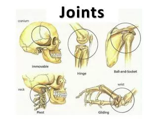
Outline • Introduction • Geometry and classification of fasteners • Types of fasteners
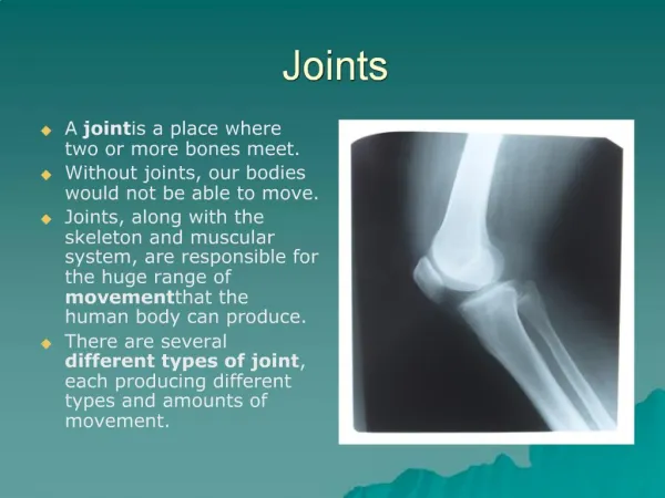
Bolted Joints Bolts find application due to ease in following • Field assembly • Disassembly • Maintenance • Adjustment • Screw Jacks for lifting and power transmission • Screws are also used for linear actuation Fun Fact: Boeing’s 747 require as many as 2.5 million fasteners
Bolted Joints • Bolted joints are connectors which affect: – Stiffness (as they are not rigid) – Vibration, Damping and Stability – Load bearing capacity • Bolted Joints are needed for disassembly – Maximum benefits are obtained when they are preloaded – Threads can plastically deform – Reusing is no recommended • Note that the assemblies using bolts can resist tensile, shear loads and moments but bolts are only designed to take tension
Geometry of Bolt Ad tw HBolt t1 ld l L t2 lt HNut tw LT At
Manufacture of Threads Rolled Threads Head Shank Cut Threads Steel is most common
Functions of Washer • Spacer • Distribute load in clamped member • Reduce head-member wear • Lower coefficient of friction/losses • Lock bolt into the joint (lock washer) • Increase preload resolution (wave washer)
Definitions • Pitch–distance between adjacent threads. Reciprocal of threads per inch • Major diameter–largest diameter of thread • Minor diameter–smallest diameter of thread • Pitch diameter–theoretical diameter between major and minor diameters, where tooth and gap are same width • The lead, l, is the distance the nut moves parallel to the screw axis when the nut is given one turn • Multiple threads are also possible Major diameter Pitch diameter Minor diameter Pitch p 45 chamfer Root Thread angle 2 Crest
Standards • The American National (Unified) thread standard defines basic thread geometry for uniformity and interchangeability • American National (Unified) thread – UN normal thread – UNR greater root radius for fatigue applications • Metric thread – M series (normal thread) – MJ series (greater root radius)
Standards • Coarse series UNC – General assembly – Frequent disassembly – Not good for vibrations – The “normal” thread to specify • Fine series UNF – Good for vibrations – Good for adjustments – Automotive and aircraft • Extra Fine series UNEF – Good for shock and large vibrations – High grade alloy – Instrumentation – Aircraft
Thread Profile Thread profile M and MJ H 8 p 8 Internal threads 3H 8 p 2 p 2 5H 8 H 60 H 4 p 4 60 H 4 d 30 dp p External threads dr
Thread Nomenclature Material grade Threads per inch Thread series ¼-20 x ¾ in UNC-2 Grade 5 Hex head bolt Nominal diameter length Class fit Head type Pitch Metric M12 x 1.75 ISO 4.8 Hex head bolt Nominal diameter Material class
*The equations and data used to develop this table have been obtained from ANSI B1.1-1974 and Coarse-Pitch Series Tensile- Minor- Pitch Stress p Area At mm mm2 Fine-Pitch Series Major Tensile- Minor- Pitch Stress Diameter p Area At mm mm2 Nominal Diameter d mm B18.3.1-1978. The minor diameter was found from the equation dr = d −1.226 869p, and the Diameter Area Ar mm2 pitch diameter from dp = d − 0.649 519p. The mean of the pitch diameter and the minor Area Ar mm2 1.6 0.35 1.27 1.07 2 2.5 3 3.5 4 5 6 8 10 12 14 16 20 24 30 36 42 48 56 64 72 80 90 100 110 0.40 0.45 0.5 0.6 0.7 0.8 1 1.25 1.5 1.75 2 2 2.5 3 3.5 4 4.5 5 5.5 6 6 6 6 6 2.07 3.39 5.03 6.78 8.78 1.79 2.98 4.47 6.00 7.75 14.2 20.1 36.6 58.0 84.3 115 157 245 353 561 817 1120 1470 2030 2680 3460 4340 5590 6990 12.7 17.9 32.8 52.3 76.3 1 39.2 61.2 92.1 36.0 56.3 86.0 116 157 259 365 596 884 1.25 1.25 1.5 1.5 1.5 2 2 2 2 2 2 2 2 1.5 2 2 2 diameter was used to compute the tensile-stress area. 104 144 225 324 519 759 1050 1380 1910 2520 3280 4140 5360 6740 125 167 272 384 621 915 1260 1670 2300 3030 3860 4850 6100 7560 9180 1230 1630 2250 2980 3800 4800 6020 7470 9080
Tensile Stress Calculations • The tensile stress area, At, is the area of an unthreaded rod with the same tensile strength as a threaded rod • It is the effective area of a threaded rod to be used for stress calculations • The diameter of this unthreaded rod is the average of the pitch diameter and the minor diameter of the threaded rod
Bolt Heads • Hexagon head bolt – Usually uses nut – Heavy duty • Socket head cap screw – Usually more precision applications – Access from the top • Machine screws – Usually smaller sizes – Slotted or Philips head common – Threaded all the way Fig. 8–9
Machine Screws 80 to 82 A A D D H L H L (a) Round head (b) Flat head 80 to 82 A A D D H L H L (c) Fillister head (d) Oval head 53 A A D D R H L L (e) Truss head ( f ) Binding head D D W W L H L H (g) Hex head (trimmed)
Hex Head Bolt • Hexagon-head bolts are one of the most common for engineering applications • Standard dimensions are included in Table A–29 (Shigley) • W is usually about 1.5 times nominal diameter • Bolt length L is measured from below the head W H Approx. 1 in 64 R 30
H Metric Bolt Sizes W R Head Type Heavy Hexagonal Square W Regular Hexagonal W H Structural Hexagonal W H Nominal Size, mm H W H Rmin Rmin Rmin M5 8 3.58 8 10 13 16 18 21 24 10.75 30 13.40 36 15.90 46 19.75 55 23.55 3.58 4.38 5.68 6.85 7.95 9.25 0.2 0.3 0.4 0.4 0.6 0.6 0.6 0.8 0.8 1.0 1.0 M6 M8 M10 21 24 27 34 41 50 60 7.95 9.25 10.75 13.40 15.90 19.75 23.55 0.6 0.6 0.6 0.8 0.8 1.0 1.0 M12 M14 27 34 41 50 60 10.75 13.40 15.90 19.75 23.55 0.6 0.8 1.0 1.2 1.5 M16 M20 M24 M30 M36
Length of Threads English Metric
Metric Thread Specifications for Steel Bolts Metric Mechanical-Property Classes for Steel Bolts, Screws, and Studs* Minimum Proof Strength,† MPa 225 Minimum Tensile Strength,† MPa 400 Minimum Yield Strength,† MPa 240 Size Range, Inclusive M5–M36 Property Class 4.6 Material Low or medium carbon Head Marking 4.6 4.8 M1.6–M16 310 420 340 Low or medium carbon 4.8 5.8 M5–M24 380 520 420 Low or medium carbon 5.8 8.8 M16–M36 600 830 660 Medium carbon, Q&T 8.8 9.8 9.8 M1.6–M16 650 900 720 Medium carbon, Q&T 10.9 Low-carbon martensite, Q&T 10.9 M5–M36 830 1040 940 12.9 M1.6–M36 970 1220 1100 Alloy, Q&T 12.9
Nuts • See Appendix A–31 for typical specifications • First three threads of nut carry majority of load • Localized plastic strain in the first thread is likely, so nuts should not be re-used in critical applications Chamfered both sides, jam nut Washer-faced, jam nut Chamfered both sides, regular Washer-faced, regular End view
Tension Loaded Fasteners • Grip length l includes everything being compressed by bolt preload, including washers • Washer under head prevents burrs at the hole from gouging into the fillet under the bolt head
Cylinder head to body • Hex-head cap screw in tapped hole used to fasten cylinder head to cylinder body • Note O-ring seal, not affecting the stiffness of the members within the grip • Only part of the threaded length of the bolt contributes to the effective grip l
Stiffness Modeling • During bolt preload – bolt is stretched – members in grip are compressed • Under an external load P – Bolt stretches further – Members in grip uncompress a bit • Joint can be modeled as a soft bolt spring in parallel with a stiff member spring
Bolt Stiffness Modeling 1 = 1 + 1 ?? ?? ???* ??+?* • Axially loaded rod, partly threaded and partly unthreaded • Each section can be considered as a spring • These are two springs in series ? = ? ?? ??= ??? ??= ?*? ?? ?* ???*? ???*+?*?? ??= h t1 t t2 lt H t ld d d lt LT l l LT ld L L (a) (b)
Bolt Stiffness ???r? ???r+?r?? ??=
Effective Grip Length • For a screw effective grip is given by Grip length: For Fig. (a): l = thickness of all material squeezed between face of bolt and face of nut ! 2 h + d/2, t2 ≥d h + t /2 , t2 < d l = For Fig. (b): h t1 lt ld H t t2 t d d LT lt l l L LT ld L (a) (b)
Member Stiffness • Model compressed members as if they are frusta spreading from the bolt head and nut to the midpoint of the grip • Each frustum has a half-apex angle of a • Find stiffness for frustum in compression D x α y y dw x t l 2 t d d d x x (b) (a)
Stiffness of the Member ⚫ With typical value of = 30º, ⚫ Use Eq. (8–20) to find stiffness for each frustum ⚫ Combine all frusta as springs in series
Stiffness of multiple layers of same material material, two identical frusta can be added in series. The entire joint can be handled with one equation, ⚫ If the grip consists of any number of members all of the same ⚫ dw is the washer face diameter ⚫ Using standard washer face diameter of 1.5d, and with = 30º,
Example Problem As shown in Fig. 8–17a, two plates are clamped by washer-faced 1/2 in-20 UNF × 1 1/2 in SAE grade 5 bolts each with a standard 1/2 N steel plain washer. (a) Determine the member spring rate km if the top plate is steel and the bottom plate is gray cast iron. (b) Using the method of conical frusta, determine the member spring rate km if both plates are steel. (c) Using Eq. (8–23), determine the member spring rate km if both plates are steel. Compare the results with part (b). (d) Determine the bolt spring rate kb
Figure 1.437 0.75 0.095 1 2 0.6725 0.0775 3 4 0.6725 1.527 (b) (a)
Solution There are three sections for stiffness : first the washer and the top frustum of steel, a portion of cast iron and the bottom frustum of cast iron 1.437 0.75 From Table A–32, the thickness of a standard 1 N plain washer is 0.095 in. (a) As shown in Fig. 8–17b, the frusta extend halfway into the joint the distance 0.6725 2 0.0775 1 2 (0.5 + 0.75 + 0.095) = 0.6725 in 0.6725 1.527 (8–20) 0.5774πEd ln (1.155t + D −d)(D + d) (1.155t + D + d)(D −d) k =
Bolt Stiffness Ad At E Adlt + Atld kb = (d ) Following the procedure of Table 8–7, the threaded length of a 0.5-in bolt is LT = 2(0.5) + 0.25 = 1.25 in. The length of the unthreaded portion is ld = 1.5 − 1.25 = 0.25 in. The length of the unthreaded portion in grip is lt = 1.345 − 1.095 in. The major diameter area is Ad = (π/4)(0.52) = 0.196 3 in . From Table 8–2, the tensile-stress area is At = 0.159 9 in2. From Eq. (8–17) 2 0.25 = 0.196 3(0.159 9)30(106) 0.196 3(1.095) + 0.159 9(0 .25) = 3.69(10 ) lbf/in k = 6 b