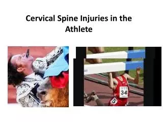
Cervical Spine Injuries
Cervical Spine Injuries. Ric Mohr. Following trauma or complaint of neck pain Obtain lateral, AP, and odontoid views The lateral view is only adequate if T1 can be visualized If there is any doubt of fracture, obtain oblique views and consider CT. Alignment.

Cervical Spine Injuries
E N D
Presentation Transcript
Cervical Spine Injuries Ric Mohr
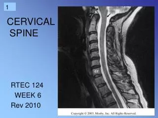
Following trauma or complaint of neck pain • Obtain lateral, AP, and odontoid views • The lateral view is only adequate if T1 can be visualized • If there is any doubt of fracture, obtain oblique views and consider CT
Predental space – should be 3mm or less Key Things to Identify
Prevertebral soft tissue May be due to hematoma from a fracture Soft tissue swelling may make fx dx difficulty
The height of the cervical vertebral bodies should be approximately equal The height of each joint space should be roughly equal at all levels. Spinous process should be in midline and in good alignment. AP View
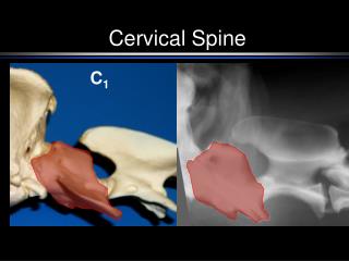
An adequate film should include the entire odontoid and the lateral borders of C1-C2. Occipital condyles should line up with the lateral masses and superior articular facet of C1. The distance from the dens to the lateral masses of C1 should be equal bilaterally. The tips of lateral mass of C1 should line up with the lateral margins of the superior articular facet of C2. The odontoid should have uninterrupted cortical margins blending with the body of C2. Odontoid View
Hangman’s Fracture • Fx through the pars reticularis of C2 secondary to hyperextension • Best seen on lateral view • Signs: • Prevertebral soft tissue swelling • Avulsion of anterior inferior corner of C2 associated with rupture of the anterior longitudinal ligament. • Anterior dislocation of the C2 vertebral body. • Bilateral C2 pars interarticularis fractures.
Jefferson Fracture • Compression fracture of the bony ring of C1, characterized by lateral masses splitting and transverse ligament tear. • Best seen on odontoid view • Signs: Displacement of the lateral masses of vertebrae C1 beyond the margins of the body of vertebra C2. • CT is required to define the extent of fracture
Odontoid Fracture • Fracture of the odontoid (dens) of C2 • 3 categories, I-III • Best seen on the lateral view • Signs: • I – Fx through superior portion of dens • II – Fx through the base of the dens • III – Fx that extends into the body of C2
Flexion Teardrop Fracture • Posterior ligament disruption and anterior compression fracture of the vertebral body which results from a severe flexion injury. • Best seen on lateral view • Signs: • Prevertebral swelling associated with anterior longitudinal ligament tear. • Teardrop fragment from anterior vertebral body avulsion fracture. • Posterior vertebral body subluxation into the spinal canal. • Spinal cord compression from vertebral body displacement. • Fracture of the spinous process.
Bilateral Facet Dislocation • Complete anterior dislocation of the vertebral body resulting from extreme hyperflexion injury. It is associated with a very high risk of cord damage. • Best seen on lateral view • Signs: • Complete anterior dislocation of affected vertebral body by half or more of the vertebral body AP diameter. • Disruption of the posterior ligament complex and the anterior longitudinal ligament. • "Bow tie" or " bat wing" appearance of the locked facets.
Unilateral Facet Dislocation • Facet joint dislocation and rupture of the apophyseal joint ligaments resulting from rotatory injury of the cervical vertebrae. • Best seen on lateral or oblique views • Signs: • Anterior dislocation of affected vertebral body by less than half of the vertebral body AP diameter. • Discordant rotation above and below involved level. • Facet within intervertebral foramen on oblique view. • Widening of the disk space. • "Bow tie" or "bat wing" appearance of the overriding locked facets.
Anterior Subluxation • Disruption of the posterior ligamentous complex resulting from hyperflexion. • Signs: • Loss of normal cervical lordosis. • Anterior displacement of the vertebral body. • Fanning of the interspinous distance.
Burst Fracture • Fracture of C3-C7 that results from axial compression. • CT is required for all patients to evaluate extent of injury.
Clay Shoveler’s Fracture • Fracture of a spinous process C6-T1 • Best seen on lateral view • Signs: • Spinous process fracture on lateral view. • Ghost sign on AP view (i.e. double spinous process of C6 or C7 resulting from displaced fractured spinous process).
Wedge Fracture • Compression fracture resulting from flexion. • Signs: • Buckled anterior cortex. • Loss of height of anterior vertebral body. • Anterosuperior fracture of vertebral body.
Summary • Key points • Lateral view • Top of T1 visible • Three smooth arcs maintained • Vertebral bodies of uniform height • Odontoid intact and closely applied to C1 • AP view • Spinous processes straight and spaced equally • Intervertebral spaces roughly equal • Odontoid view • Odontoid intact • Equal spaces on either side of odontoid • Lateral margins of C1 and C2 align