Overview - Object-Oriented Analysis and Design
Overview - Object-Oriented Analysis and Design. Design thinking Object Modeling Technique Object-Oriented Analysis Object-Oriented Design Three models Object model Dynamic model Functional model Four phases. Design Goals . Design transforms requirements into an architecture diagram

Overview - Object-Oriented Analysis and Design
E N D
Presentation Transcript
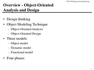
Overview - Object-Oriented Analysis and Design • Design thinking • Object Modeling Technique • Object-Oriented Analysis • Object-Oriented Design • Three models • Object model • Dynamic model • Functional model • Four phases
Design Goals • Design transforms requirements into • an architecture diagram • subsystems, modules and their relationships • a detailed design • a specification of the abstract interface, data structures, and algorithms of each module • Also develops • a review plan for ensuring the design meets the requirements • a test plan for ensuring the implementation meets the design
Object-Oriented Software Development • Object-Oriented Methodology • development approach used to build complex systems using the concepts of object, class, polymorphism, and inheritance with a view towards reusability • encourages software engineers to think of the problem in terms of the application domain early and apply a consistent approach throughout the entire life-cycle • Object-Oriented Analysis and Design • analysis models the “real-world” requirements, independent of the implementation environment • design applies object-oriented concepts to develop and communicate the architecture and details of how to meet requirements
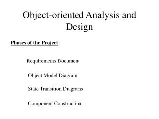
Object Modeling Technique Process via UML • OMT [Rumbaugh et al.,1991] consists of • building three complementary models of the system • adding implementation details to the models • implementing the models • OMT includes a set of • phases [processes] • diagramming techniques • OMT has four phases • object-oriented analysis builds a real-world model • system design determines overall architecture of system • object design decides upon data structures and algorithms • implementation translates design into programming language
OMT Stages and Models Analysis - Model of real-world situation - What ? System Design - Overall architecture (sub-systems) Object Design - Refinement of Design - Algorithms/data structures to implement each class Implementation - Translation of object classes and relationships to a particular object-oriented language Functional Model - Data value transformations (dataflow diagrams) Object Model - Static structure of objects and their relationships (object diagram) Dynamic Model - Control aspects of the system (state diagrams) time System
Semi-formal technique class modeling dynamic modeling functional modeling These steps focus on data actions their relationships Reuses familiar tools E-R diagrams Finite State Machines Data flow diagrams Steps and diagrams typically performed in parallel after initial class definition must be kept in synch Introduction to Object-Oriented Analysis • Object-Oriented Analysis is the “requirements phase” of Object-Oriented Software Development • think of it as an alternative semi-formal technique
Object-Oriented Analysis • Builds a “real-world” model from requirements • client interviews, domain knowledge, real-world experience collected in use cases and other simple notations • OOA models address three aspects of the system (its objects) • class structure and relationships • sequencing of interactions and events • data transformations and computations
Class Model static structure what objects are in the system? how are they related? Dynamic Model behavioral aspects what events occur in the system when do they occur and in what order? Functional Model data transformations “what” does the system do Data-Oriented Action-Oriented Both Data and Actions Models of Object-Oriented Analysis (cf UML)
OO Analysis and Design: Steps • Class Modeling • Dynamic Modeling • Functional Modeling • Add Operations to the Class Model • Iterate and refine the models • After the first iteration, steps may occur in parallelor out of order • All models must be kept in synch as changes are made
Class Modeling • Identify objects and classes • Prepare a data dictionary • Identify associations between objects • Identify class attributes and initial set of operations • Organize object classes using inheritance
Classes, Attributes and Operations • Attributes define the properties of the objects • every instance of the class has the same attributes • an attribute has a data type • the values of the attributes may differ among instances • Operations define the behavior of the objects • action performed on or by an object • available for all instances of the class • need not be unique among classes Class Attributes Operations ball radius, weight catch, throw football air pressure pass, kick, hand-off baseball liveness hit, pitch, tag
Object Model Notation (refresher) Class Name Classes are represented as rectangles; The class name is at the top, followed by attributes (instance variables) and methods (operations) Depending on context some information can be hidden such as types or method arguments InstanceVariable1 InstanceVariable2: type Method1() Method2(arguments) return type Objects are represented as rounded rectangles; The object’s name is its classname surrounded by parentheses Instance variables can display the values that they have been assigned; pointer types will often point (not shown) to the object being referenced (Class Name) InstanceVariable1 = value InstanceVariable2: type Method1() Method2(arguments) return type
OMT Instantiation Notation Class Name attribute_1: data_type_1 = default_1 attribute_2: data_type_2 = default_2 . . . attribute_m: data_type_m = default_m Class (Class Name) attribute_1 = value_1 attribute_2 = value _2 . . . attribute_m = value _m Instance
Instantiation - Example Person (Person) name age weight Joe Smith age=39 weight=158 (Person) Mary Wilson age=27 weight=121
Inheritance • Classes with similar attributes and operations may be organized hierarchically • Common attributes and operations are factored out and assigned to a broad superclass (generalization) • generalization is the “is-a” relationship • superclasses are ancestors, subclasses are descendants • Classes iteratively refined into subclasses that inherit the attributes and operations of the superclass (specialization) • Do you see any disadvantages to inheritance?
OMT Inheritance Notation Generalization Superclass Class Attributes Operations Ball Radius, Weight Throw, Catch Subclasses Football air pressure pass, kick, hand-off Baseball liveness hit, pitch, tag Basketball air pressure , dimples shoot, dribble, pass Specialization
Association and Links • An association is a relation among two or more classes describing a group of links, with common structure and semantics • A link is a relationship or connection between objects and is an instance of an association • A link or association is inherently bi-directional • the name may imply a direction, but it can usually be inverted • the diagram is usually drawn to read the link or association from left to right or top to bottom • A role is one end of an association • roles may have names
OMT Association Notation Class, Association, and Roles Company Person Works For equivalent Company Person Employs Employer Employee Object and Link (Person) (Company) Works For IBM Johnson
Association and Links has-capital Country City Class diagram name name (Country) has-capital (City) Canada Ottawa (Country) has-capital (City) Instance diagram France Paris (Country) has-capital (City) Austria Vienna
Multiplicity of Associations • Multiplicity is the number of instances of one class that may relate to a single instance of an associated class • 1-to-1 • 1-to-many (0 or more) • 1-to-(zero-or-one) ‘optional’ • 1-to-(one-or-more) ‘required’ • 1-to-n 1+ n
OMT Multiplicity Notation Instructor Courses 1+ Teaches Takes 6-65 Student Each course has at least one instructor and between 6 and 65 students A student may take many courses An instructor may teach many courses
Link attributes for associations works-for Person Company name name address salary job title
Aggregation • Aggregation is a special form of association that indicates a “part-of” relationship between a whole and its parts • Useful when the parts do not have independent existence • A part is subordinate to the whole • In an aggregation, properties and operations may be propagated from the whole to its parts
OMT Aggregation Notation Window TitleBar ScrollBar Border
Multilevel aggregation Microcomputer 1+ Mouse Keyboard Monitor System box 1+ 1+ Chassis CPU RAM Fan
An Example FastData Inc. wants a subsystem to process office supply orders via the Web. The user will supply via a form their name, password, account number, and a list of supplies along with an indication of the quantities desired. The subsystem will validate the input, enter the order into a database, and generate a receipt with the order number, expected ship date, and the total cost of the order. If the validation step fails, the subsystem will generate an error message describing the cause of the failure.
Purpose of Example • We will demonstrate the UML /OMT using this example • Class modeling will be done first • Dynamic and Functional modeling will occur next lecture • Detailed design will also occur next lecture • Things to remember • This example does not demonstrate how the technique is applied to ALL problems. Be sure to distinguish between the details of the example and the details of the technique!
Concise Problem Definition • Define the problem concisely • Use only a single sentence “FastData, Inc. employees may order office supplies via the Web and receive a receipt confirming the order” • This is the first step towards identifying the classes of the subsystem
Informal Strategy • Identify the constraints governing the system • Use only a single paragraph “FastData, Inc. employees may order office supplies via the Internal Web and receive a receipt confirming the order. The order must include the user name, user password, account number, and the list of supplies. A receipt must be generated containing an order number, ship date, and total cost. If the order is valid, it must be entered into an order database. If the order is invalid, an error message must be generated.” • We now have more information to be used in identifying classes for the subsystem
Formalize the Strategy • Identify the nouns of the description, which serve as the basis for identifying the subsystem’s classes. • Look for out-of-domain nouns (and throw them out!) • Look for abstract nouns (use these for attributes) • The remaining nouns are good candidates! “FastData, Inc. employees may order office supplies via the Internal Web and receive a receipt confirming the order. The order must include the user name, user password, account number, and the list of supplies. A receipt must be generated containing an order number, ship date, and total cost. If the order is valid, it must be entered into an order database. If the order is invalid, an error message must be generated.”
Out-of-Domain Internal Web Abstract user name user password account number order number ship date total cost list of supplies office supplies -> item Good Candidates employee item (was office supplies) receipt order order database error message Notes We have decided not to worry about the Web in this design. Instead we focus on the inputs and outputs and defer the Web details until later. Nouns
employee order DB order name password number account total cost error message receipt item order number ship date total cost name quantity price explanation Class Model
response error message receipt order number ship date total cost explanation Class Model, continued Since both receipts and error messages will be generated as output it might make sense to have them as subclasses of a more general class. We do not know enough yet to assign it attributes however.
employee order DB order name password number account total cost error message receipt item order number ship date total cost name quantity price explanation Class Model, relationships 1+
Overview - Object-Oriented Analysis and Design • Three models • Object model • Dynamic model • Functional model • Four phases • object-oriented analysis • system design • object design • Implementation • Detailed Design • Integration Testing
OMT Analysis and Design: Steps • Class Modeling • Dynamic Modeling • Functional Modeling • Add Operations to the Class Model • Iterate and refine the models • After the first iteration, steps may occur in parallelor out of order • All models must be kept in synch as changes are made
Dynamic Modeling • Prepare scenarios • Identify events between objects • Prepare an event trace for each scenario • Build a state diagram • Match events between objects to verify consistency
Dynamic Model Diagrams • The dynamic model tracks behavior over time • described in terms of change in objects or event sequences between objects • Event Trace Diagrams • show typical dialog or usage scenarios as well as exceptional and/or special cases • State Diagrams • relates events, states, and state transitions • a scenario is a path through the state diagram
Events and Scenarios • An event is [an ‘instantaneous’ change of state in the application domain] that triggers a change to an object’s object state (?) • events have attributes, which are the information transferred from one object to another • A scenario is a specific sequence of events representing a path through a system’s state space • Legitimate scenarios • common paths (e.g. frequently used functionality) • Error conditions and known exceptions • An event trace extends the scenario to clarify events between objects
Event Classes airplane departs (airline, flight number, city) mouse button pushed (button, location) phone receiver lifted digit dialed (digit) Events United Flight 23 departs from Rome right mouse button pushed at (29, 30) phone receiver lifted digit dialed (2) Event classes and attributes
An example scenario • Scenario for a phone call • caller lifts receiver • dial tone begins • caller dials digit (2) • caller dials digit (7) • caller dials digit (7) • caller dials digit (6) • specified phone rings • etc.
arrows indicate sender and receiver time passes from top to bottom objects are vertical lines events are horizontal lines Customer Pump Credit Corp “select method of payment” select “credit” insert card slide card through reader verify account return “approved” “select grade” select “premium” “pump on” display unit cost, total cost, gallons dispensed pump gas update display with total cost, gallons dispensed charge total cost to account OMT Event Trace Notation
Event Trace: example Caller Phone line Callee caller lifts receiver dial tone begins dials (2) dial tone ends dials (7) dials (7) dials (6) ringing tone phone rings answers phone phones connected phones connected callee hangs up connection broken connection broken caller hangs up
States and Transitions • A state is an interval between events (values of relevant variables to the problem…) • it may have an activity that can trigger starting, intermediate and ending events • defined in terms of a subset of object attributes and links • A state transition is a change in an object’s attributes and links • it is the response of an object to an event • all transitions leaving a state must correspond to distinct events
OMT State Notation • states represented as nodes: rounded rectangles with state name • initial state represented as solid circle • final state represented as bull’s eye • transitions represented as edges between nodes and labeled with an event name Event-b STATE-1 STATE-2 Event-a Event-c Event-e Event-d result STATE-3
OMT State Diagram - Example Chess game checkmate White´s turn Black wins Start stalemate black moves white moves Draw stalemate Black´s turn White wins checkmate
Guards, Activities and Actions • Guards are boolean conditions on attribute values • transition can only happen when guard evaluates to “true” • automatic transitions occur as soon as an activity is complete (check guard!) • Activities take time to complete • activities take place within a ‘state’ • Actions are relatively instantaneous • actions take place on a transition or within a state (entry, exit, event actions) • output can occur with an event [guard-1] A-STATE entry / entry-action do: activity-A event-1 / action-1 ... exit / exit-action STATE-1 action-Event / action output-Event / output guarded-Event [guard-2] STATE-2
Guards, Activities and Actions - Example Vending machine model coins in (amount) / set balance Collecting money Idle cancel / refund coins coins in (amount) / add to balance select (item) [item empty] [change < 0] do: test item and compute change [change = 0] [change > 0] do: dispense item do: make change
States can be nested or concurrent Events can be split and merged OMT State Relationships event-1 Superstate (nesting) Superstate (concurrency) event-1 substate-1 substate-3 substate-1 substate-2 event-2 substate-2 substate-4 event-3 event-2 (Synchronization) event-1 substate-3 substate-1 merged-event-3 split-event-0 event-2 merged-event-4 substate-2 substate-4
State Generalization: example Transmission push N Neutral Reverse push R push N push F Forward upshift upshift stop First Second Third downshift downshift