SkyMax Aerotech Wireless Automation Manual
160 likes | 222 Vues
Skymax Aerotech Series Opening Louvred Roofs are manufactured to your specifications and are available in a sophisticated range of colours and finishes.

SkyMax Aerotech Wireless Automation Manual
E N D
Presentation Transcript
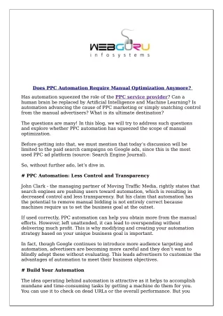
Aerotech Opening Louvred Roof - Wireless Automation Manual Electronic device with radio receiver to control 230Vac motors for Aerotech Roofs Characteristics of the product • Self-learning procedure for limits and working time • Independent or synchronized command of the motors • Automatic adjustable blade tilting • Automatic or hold-to-run radio commands • Plug-in board to control the LED lights (optional) Sensors • Rain • Anemometer for wind speed & ventilation control • Temperature to prevent the heat-gain to your building • Combination of rain and temperature sensors to control blinds, heaters & lighting Warning: The product must be installed only by qualified technician in accordance with the rules concerning the automatic covers. The system is powered at 230Vac. Model number T588.07_EN Code Number: TVPLAxxxAC2 Series Date TVLink 02/07/14 1
Correlated products Plug-in boards for LED control TVSTRD00PSI24 for 1-colour LED lightings. Independent or simultaneous control of 3 output (max. 60W each). 24Vdc power supply. TVRGB00PSI24 for RGB (red, green, blue) LED lightings. 24Vdc power supply (max. 60W each of 3 output). TVRGBW00PSI24 for RGB+W (red, green, blue + white) LED lightings. Independent control of RGB output and White output, by means of different memorization of transmitter channels. 24Vdc power supply (max. 60W each of 4 output). EVO Transmitter TVEVO868N42P 42 channels hand transmitter with wall fixing support, ideal for multi-group commands. + group - group selection selection colors 1 colors 2 closing slat Control of: motors for roofs opening slat 1 • • • • • • opening slat 2 RGB lightings 1-colour lightings 230V lightings ventilation-heating screens opening slat 3 OPEN STOP colors 1 or 2 selection cycle activation preset 1 - 2 - 3 - 4 increase/decrease CLOSE OFF GREEN MOUSE Wall/table transmitter with light sensor TVTSL868N30 Wireless transmitter for the automatic control of the brightness in a room or under a pergola covering. The user can adjust the brightness of the location simply commanding the screen or the pergola through the buttons, saving the desired level. The level will be automatically kept in the time by Green Mouse, as the variation of the natural light. WIND SENSOR RAIN SENSOR TEMPERATURE PROBE ANEM4 TMP150 RAIN101 Model number T588.07_EN Code Number: TVPLAxxxAC2 Series Date TVLink 02/07/14 2
Index 1 Wiring and adjustments ----------------------------------------------------------- ----------------------------------------------------------- page 4 2 Control unit configuration page 5 - 7 • • • Pergola with 1 motor Pergola with 2 independent motors Pergola with 2 synchronized motors 3 Transmitters memorization ----------------------------------------------------------- page 8 - 9 3.1 Memorization of 7 channels transmitter 3.2 Memorization of automatic commands in pair 3.3 Memorization and use of Green Mouse 3.4 Memorization of hold-to-run commands in pair 3.5 Memorization of a transmitter with an already memorized transmitter 4 Transmitters deletion ----------------------------------------------------------- page 10 4.1 Deleting a transmitter 4.2 Deleting a transmitter with an already memorized transmitter 4.3 Deleting all the transmitters 5 Sensors ----------------------------------------------------------------------------------------- page 11 - 12 5.1 Wind sensor 5.2 Wind sensor threshold 5.3 Rain sensor 5.4 Activation/Deactivation of the rain sensor using a transmitter 5.5 Temperature sensor 5.6 Activation/Deactivation of the temperature sensor 5.7 Snow condition: temperature sensor combined with rain sensor 5.8 Activation/Deactivation of the combination of temperature and rain sensors 6 Memorization of the user angles -------------------------------------------------- page 13 page 14 7 Troubleshooting --------------------------------------------------------------------- ----------------------------------------------------------- 7.1 Replacing the product 8 Technical specifications page 15 Warnings The above mentioned product must be installed only by qualified technical personnel in compliance with the standards of automatic openings. All connections must be rated for a single-phase power supply of 230V. For the disconnection from the power line, use an all-pole switch with contact with an opening of at least 3.5 mm. Only suitable materials for the connections must be used to guarantee insulation that complies with current standards on the subject of electrical safety. The product executes just movement controls; all the necessary safety devices are to be seen separately. Incorrect wiring will cause incorrect functioning impairing the safety purpose for which the product has been designed so that people injuries could occur; failure to follow instructions can cause personal injury and/or property damage. Keep the 230V wires from the low voltage safety wires separately. The earth-wires must be fixed by means of an additional fastening nearby the terminals; this fastening has to be done by qualified technical personnel during the installation phase. The appliance has been tested with a power supply wire type H05VV-F; the power supply wires for outdoor use must have better characteristics than the ordinary wires type H05RN-F. The safety devices have to be in conformity with EN12978. The product is in conformity with the RAEE and RoHS directive. In the view of a constant development of their products, the manufacturer reserves the right for changing technical data and features without prior notice. Model number T588.07_EN Code Number: TVPLAxxxAC2 Series Date TVLink 02/07/14 3
1. Wiring and adjustments Memory (par. 7.1) P1 and P2 Dip switch DSW1 L1 AERIAL 230Vac P1 P2 RAIN sensor Temperature sensor L2 L3 WIND sensor Memoria Plug-in board for LED lights (optional) Attention! Power supply for plug-in board (12-24Vdc) The 230Vac input of the electronic board and the motors output are protected by a 5A fuse. M1 M2 IN Ground connections between motors and input SIGNAL 16 RF AERIAL 1 2 3 4 5 6 7 8 230 Vac (Line) 17 GND AERIAL 230 Vac (Neutral) 18 TEMPERATURE SENSOR (BLACK) 19 TEMPERATURE SENSOR (WHITE) 22 GND CLOSING MOTOR 1 COMMON MOTOR 1 OPENING MOTOR 1 OPENING MOTOR 2 COMMON MOTOR 2 CLOSING MOTOR 2 23 12-24Vdc (Plug-in board for LED lights) DIP 1-2-3 Setting of wind sensor threshold Motor control mode: 11 WIND SENSOR (BLUE) 12 WIND SENSOR (BROWN) 13 RAIN SENSOR (WHITE,12V) 14 RAIN SENSOR (BLUE, signal) 15 RAIN SENSOR (YELLOW, GND) Synchronized, two motors mechanically connected or controlled at the same time Independent, one or two motors not mechanically connected DIP 4-5 LED COLOUR STATUS MEANING L1 L2 RED RED ON Power ON Priority Flashes sequences: One flash every 10 sec. Two quick flashes every 10 sec. Three quick flashes every 10 sec. Four quick flashes every 10 sec. Five quick flashes ALARMS: Water draining alarm (par. 5.3) Rain alarm (par. 5.3) Ice / Snow alarm (par. 5.5 - 5.7) Wind alarm (par. 5.1) Built-in motor limit switch activated Synchronized Mode activated Synchronized Mode activated (during the configuration) Independent Mode activated (during the configuration) L3 BLUE ON One flash every sec. One flash every 2 sec. Model number T588.07_EN Code Number: TVPLAxxxAC2 Series Date TVLink 02/07/14 4
2. Control unit configuration At the first power-on, the control unit emits an intermittent sound for 2 minutes and L3 flashes, this means that the system needs to be configured. After recognizing the right product application among the 3 reported below, follow the proper configuration procedure. Attention: in case of a wrong selection of the application it will be necessary to repeat the correct configuration procedure. Aerotech Opening Louvred Roof With 1 Motor 1. CONFIGURATION OF MOTOR 1 1.1 Set DIP4 and DIP5 to OFF. ON 1 2 3 4 5 6 1 1.2 Press at the same time P1 and P2 for 5 seconds, the buzzer emits an intermittent sound and L3 flashes. P1 + P2 ... 5 sec. 1 1.3 Move motor 1 with P1 (closing) and P2 (opening). If the direction is wrong, invert the wires corresponding to the motor phases (terminals 3 and 5). 1.4 Check that the manoeuvre stops because of current absorption threshold (L2 ON) only when the limit switch is reached. 2. SELF-LEARNING OF THE LIMITS 2.1 Press quickly 2 times P1 and P2 at the same time, keeping pressed the second time for 5 seconds, the buzzer emits a fast intermittent sound. P1 + P2 P1 + P2 ... 5 sec. < 1 sec. The control unit automatically performs the following steps: • • Self-learning of complete closing. Self-learning of complete opening. Each step the buzzer emits faster intermittent sounds, at the end it stops. 2.2 DO NOT change the DIP configuration. This modification would be signalled by a new intermittent sound and the flashing of L3, and it would require a new configuration procedure. Model number T588.07_EN Code Number: TVPLAxxxAC2 Series Date TVLink 02/07/14 5
Pergola with 2 independent motors 1. CONFIGURATION OF MOTOR 1 1.1 Set DIP4 and DIP5 to OFF. ON 2 1 2 3 4 5 6 1.2 Press at the same time P1 and P2 for 5 seconds, the buzzer emits an intermittent sound and L3 flashes. 1 P1 + P2 ... 5 sec. 1 2 1.3 Move motor 1 with P1 (closing) and P2 (opening). If the direction is wrong, invert the wires corresponding to the motor phases (terminals 3 and 5). 1.4 Check that the manoeuvre stops because of current absorption threshold (L2 ON) only when the limit switch is reached. 2. CONFIGURATION OF MOTOR 2 2.1 Set DIP4 to ON and DIP5 to OFF. ON 1 2 3 4 5 6 2.2 Move motor 2 with P1 (closing) and P2 (opening). If the direction is wrong, invert the wires corresponding to the motor phases (terminals 6 and 8). 2.3 Check that the manoeuvre stops because of current absorption threshold (L2 ON) only when the limit switch is reached. 3. SELF-LEARNING OF THE LIMITS 3.1 Press quickly 2 times P1 and P2 at the same time, keeping pressed the second time for 5 seconds, the buzzer emits a fast intermittent sound. P1 + P2 P1 + P2 ... 5 sec. < 1 sec. The control unit automatically performs the following steps, first for motor 1 then for motor 2: • • Self-learning of complete closing. Self-learning of complete opening. Each step the buzzer emits faster intermittent sounds, at the end it stops. 3.2 DO NOT change the DIP configuration. This modification would be signalled by a new intermittent sound and the flashing of L3, and it would require a new configuration procedure. Model number T588.07_EN Code Number: TVPLAxxxAC2 Series Date TVLink 02/07/14 6
Pergola with 2 synchronized motors 1. CONFIGURATION OF MOTOR 1 AND MOTOR 2 1.1 Set DIP4 to OFF and DIP5 to ON. ON 1 2 3 4 5 6 1 + 2 1+2 1.2 Press at the same time P1 and P2 for 5 seconds, the buzzer emits an intermittent sound and L3 flashes. P1 + P2 ... 5 sec. 1.3 Move the motors together with P1 (closing) and P2 (opening). If the direction is wrong, invert the wires corresponding to the motor phases (terminals 3-5 for motor 1, 6-8 for motor 2). 1.4 Check that the manoeuvre stops because of current absorption threshold (L2 ON) only when the limit switch are reached. 2. SELF-LEARNING OF THE LIMITS 2.1 Press quickly 2 times P1 and P2 at the same time, keeping pressed the second time for 5 seconds, the buzzer emits a fast intermittent sound. P1 + P2 P1 + P2 ... 5 sec. < 1 sec. The control unit automatically performs the following steps, for both motors at the same time: • • Self-learning of complete closing. Self-learning of complete opening. Each step the buzzer emits faster intermittent sounds, at the end it stops. 2.2 DO NOT change the DIP configuration. This modification would be signalled by a new intermittent sound and the flashing of L3, and it would require a new configuration procedure. Model number T588.07_EN Code Number: TVPLAxxxAC2 Series Date TVLink 02/07/14 7
3. Transmitter memorization If the system is configured as Roofwith 2 independent motors, it connects the memorization by pressing P1 to motor 1 and P2 to motor 2. In the other configurations the memorization is possible using both P1 or P2. If the system is configured as Roofwith 2 independent motors, any radio code can be associated to both motors, memorizing it using P1 (Motor 1) first, then P2 (Motor 2). 3.1 Memorization of 7 channels transmitter This configuration permits the control of the system with a 7 channel transmitter, in which every channel is connected to a single operation: 0 % (CLOSED) 33 % CH1 CH2 CH3 CH4 CH5 CH6 CH7 66 % 100 % (OPEN) Hold-to-run opening STOP Hold-to-run closing < 1 sec. • Press 2 times P1 or P2 (according to the motor control mode) keeping pressed the second time. • • The buzzer emits a continuous sound. Press any button of transmitter. Once the memorization is successfully completed, the buzzer emits a fast intermittent sound. ... ... P1 or P2 last ----- 2 TIMES ----- 3.2 Memorization of automatic commands in pair This configuration permits the control of the system with a transmitter of at least 2 channels. Pressing a button the system stops if the motor is moving in the opposite direction. Opening (STOP) Opening (STOP) Closing (STOP) Opening (STOP) Closing (STOP) Opening CH1 CH2 CH3 CH4 CH5 CH6 CH7 Opening STOP CH5 Closing (STOP) CH6 CH7 STOP Closing Closing 7 channels transmitter < 1 sec. 3 channels transmitter 2 channels transmitter • • • Press 3 times P1 or P2 (according to the motor control mode) keeping pressed the third time. The buzzer emits a continuous sound. Press any button of the pair to memorize. Once the memorization is successfully completed, the buzzer emits a fast intermittent sound. ... ... P1 or P2 last ----- 3 TIMES ----- Model number T588.07_EN Code Number: TVPLAxxxAC2 Series Date TVLink 02/07/14 8
3.3 Memorization and use of Green Mouse (see details at page 2) Memorization Complete the following two steps to memorize Green Mouse: 1. Carry out the procedure 3.2, pressing button 2 or 3. 2. Carry out the procedure 3.2, pressing button 2 and 3 at the same time. 1 2 6 3 4 Use (see the instructions manual of the product for further details) 1. Choose the desired light level by opening or closing the 5 application with buttons 2 and 3. 2. Store the desired level with button 4. 1 - Light s 2 - OPEN 3. Green Mouse will keep the set light level moving automatically 3 - CLOSE button 4 - Light level memorization button 5 - Activation/deactivation light control button 6 - Signal and programming LED (red, blue) the application to let the natural light in. 4. Use button 5 to activate/deactivate the control at any time. 3.4 Memorization of hold-to-run commands in pair This configuration permits the control of the system with a transmitter of at least 2 channels. The system commands a movement only if the button is kept pressed. Hold-to-run Hold-to-run opening Hold-to-run closing Hold-to-run opening Hold-to-run closing Hold-to-run opening STOP opening CH1 CH2 CH3 CH4 CH5 CH6 CH7 Hold-to-run opening STOP CH5 CH6 CH7 Hold-to-run closing Hold-to-run closing Hold-to-run closing 7 channels transmitter 3 channels transmitter 2 channels transmitter < 1 sec. • • • Press 4 times P1 or P2 (according to the motor control mode) keeping pressed the fourth time. The buzzer emits a continuous sound. Press any button of the pair to memorize. Once the memorization is successfully completed, the buzzer emits a fast intermittent sound. ... ... P1 or P2 last ----- 4 TIMES ----- 3.5 Memorization of a transmitter with an already memorized transmitter The new transmitter must have the same (or higher) number of buttons as the memorized one. At the end of procedure it will have the same functioning of the memorized transmitter. Memorized Memorized NEW • Press P3 of the transmitter already memorized. The buzzer emits a continuous sound. • Press the button of the pair or any in a 7 channels transmitter to copy. The buzzer stops for 1 second and emits the sound again. • • Press the button to memorize of the new transmitter. Once the memorization is successfully completed, the buzzer emits a fast intermittent sound. ... 1 sec. within 5 sec. within 5 sec. Model number T588.07_EN Code Number: TVPLAxxxAC2 Series Date TVLink 02/07/14 9
4. Transmitters deletion If the system is configured as a Roofwith 2 independent motors, it connects the deletion by pressing P1 to motor 1 and P2 to motor 2. In the other configurations the deletion is possible using both P1 or P2. 4.1 Deleting a transmitter < 1 sec. • • Press 5 times P1 or P2 (according to the motor control mode) keeping pressed the fifth time. The buzzer emits a continuous sound. Press the button of the pair or any in a 7 channels transmitter to delete within 10 seconds. Once the memorization is successfully completed, the buzzer emits a fast intermittent sound. ... ... P1 or P2 last • ----- 5 TIMES ----- within 10 sec. 4.2 Deleting a transmitter with an already memorized transmitter Memorized To delete • • • Press P3 of the transmitter already memorized. The buzzer emits a continuous sound. Press the button of the pair or any in a 7 channels transmitter to delete within 10 seconds. Once the memorization is successfully completed, the buzzer stops sounding. P3 3 times ... within 5 sec. 4.3 Deleting all the transmitters < 1 sec. • • • Press 6 times P1 or P2 keeping pressed the sixth time. The buzzer emits a fast intermittent sound for about 10 sec. Release when the sound becomes continuous. 10 sec. ... ... P1 or P2 last ----- 6 TIMES ----- Model number T588.07_EN Code Number: TVPLAxxxAC2 Series Date TVLink 02/07/14 10
5.1 Wind sensor The wind sensor (ANEM4, 4 pulses/rotation) detects the wind speed. It has the highest priority among the sensors. If the alarm is active, the control unit moves the slats at 33% of the opening. The device does not perform any command during the status of alarm and it resumes its normal operation when the alarm is not active anymore. The alarm is off when the sensor detects for 60 seconds a speed lower than the set threshold. 5.2 Wind sensor threshold DIP 1 DIP 2 DIP 3 Km/h 40 OFF OFF OFF OFF ON OFF OFF ON OFF ON 45 With DIP SWITCH 1, 2 and 3 it is possible to set the wind speed alarm threshold (Km/h): OFF ON 50 ON 55 OFF OFF ON OFF ON 60 ON 65 ON OFF ON 70 ON ON 75 5.3 Rain sensor When the sensor detects the rain and the alarm is activated, the device positions the slats of the Roofin closed position. The device doesn’t perform any command during the status of alarm. The alarm is off when the sensor doesn’t detect the presence of the rain for 20 seconds. By default the sensor is activated. Functioning of the system AFTER the rain alarm (Water draining) Once the rain alarm is off, for the next 6 hours, as soon as a command of automatic movement sent by transmitter is received, the control unit will move the slats to 25%, to allow the water draining. For 4 minutes the control unit will perform just hold-to-run commands, switching off the alarm status. 5.4Activation/Deactivation of the rain sensor using a transmitter In order to perform this procedure at least one transmitter must be memorized (par. 3), and it must be performed when the system is stopped. By default the sensor is activated. 10 sec. 10 sec. 4 sec. Activation Deactivation Press for 10 sec. the button “STOP” of transmitter. The buzzer emits for 4 sec. a continuous sound. Press for 10 sec. the button “STOP” of transmitter. The buzzer emits 2 beeps. Model number T588.07_EN Code Number: TVPLAxxxAC2 Series Date TVLink 02/07/14 11
5.5 Temperature sensor The sensor (NTC 10K/3435K) detects the temperature that could cause the freezing of the pergola slats. If it is under 2°C the alarm is activated, then the control unit moves the slats at the 66% of the opening. The alarm is off when the temperature is over 3°C. The control unit performs just hold-to-run commands during the status of alarm, and resumes its normal operation when the alarm is not active anymore. By default the sensor is deactivated. 5.6 Activation/deactivation of the temperature sensor < 1 sec. < 1 sec. ... ... P1 last 5 sec. P1 last 5 sec. ----- 7 TIMES ----- ----- 7 TIMES ----- Activation (possible only if the sensor is connected) Deactivation • Press 7 times P1 keeping pressed the seventh time • Press 7 times P1 keeping pressed the seventh for 5 sec. time for 5 sec. • The buzzer emits for 4 sec. a continuous sound. • The buzzer emits 2 beeps. 5.7 Snow condition: temperature sensor combined with rain sensor To manage the alarm related to the condition of snow it’s necessary combine temperature sensor and rain sensor. The alarm is on when the temperature is under 2°C and the rain has been detected, then the control unit moves the slats at the 66% of the opening. The alarm is off when the temperature is over 3°C or when there is no rain detection. The control unit performs just hold-to-run commands during the status of alarm, and resumes its normal operation when the alarm is not active anymore. By default the combination is deactivated. 5.8Activation/Deactivation of the combination of temperature and rain sensors < 1 sec. < 1 sec. ... ... P2 last 5 sec. P2 last 5 sec. ----- 7 TIMES ----- ----- 7 TIMES ----- Activation of Rainconfiguration (possible only Deactivation of Rainconfiguration if the temperature sensor is connected) • Press 7 times P2 keeping pressed the seventh time for 5 sec. • Press 7 times P2 keeping pressed the seventh time for 5 sec. • The buzzer emits a continuous sound. • The buzzer emits 3 beeps. Note: Once the Rainconfiguration is deactivated, the control unit considers the previous activation/deactivation status of the rain sensor and temperature sensor. Model number T588.07_EN Code Number: TVPLAxxxAC2 Series Date TVLink 02/07/14 12
6. Memorization of the user angles Use the following procedure to modify the default angles of the Roof Blades related to the wind alarm (33%) or the temperature/rain alarm (66%). After the system configuration and having memorized at least one transmitter, use this to move the Roof blades to the desired angle, then: Wind alarm angle < 1 sec. • • Press 8 times P1 or P2 (according to the motor control mode) keeping pressed the eighth time for 5 sec. The buzzer emits for 1 sec. a continuous sound. ... • Roof automatically closes last 5 sec. P1 or P2 1 sec. ----- 8 TIMES ----- Temperature/rainangle < 1 sec. • Press 9 times P1 or P2 (according to the motor control mode) keeping pressed the ninth time for 5 sec. The buzzer emits for 2 sec. a continuous sound. • • ... Pergola automatically closes P1 or P2 last 5 sec. 2 sec. ----- 9 TIMES ----- Reset the angles to factory setting < 1 sec. • • Press 10 times P1 or P2 keeping pressed the tenth time for 5 sec. The buzzer emits for 3 sec. a continuous sound. ... last 5 sec. P1 or P2 3 sec. ----- 10 TIMES ----- Model number T588.07_EN Code Number: TVPLAxxxAC2 Series Date 02/07/14 TVLink 13
7. Troubleshooting Problem Solution At the power-on the control unit emits an intermittent sound and L3 flashes. The sound is still present after the configuration (and L3 flashes). The system needs to be configured. Refer to chapter 2. Repeat the procedure at chapter 2. DO NOT move the DIP setting after the procedure. P1 and P2 must be pressed at the same time. The time between the first and the second pressure must be less than 1 sec. The configuration procedure doesn’t start pressing two times P1 and P2. There’s no continuous beep during a transmitter memorization. The time between a pressure and the next one must be less than 1 sec. It’s not possible to memorize a transmitter. The code is already in the memory or the memory is full. 7.1 Replacing the product In case of defective control unit, and if the memory is still working, it’s possible to replace the control unit keeping all the settings memorized previously. Remove the defective control unit and replace it with a new one; when the control unit is switched off, insert the memory of the defective control unit to the new one and set all the DIP as they were in the old control unit. Switch the system on. Model number T588.07_EN Code Number: TVPLAxxxAC2 Series Date TVLink 02/07/14 14
8. Technical specifications Attention! The 230Vac input of the electronic board and the motors output are protected by a 5A fuse. - Reception frequency 868,3 MHz (TVPLA868AC2) 916 MHz (TVPLA916AC2) 230 Vac - Power supply - Single output AC motor - Fuse protection - Operating temperature range - Max. number of transmitters 230 Vac - max. 1,5 A 5A ritardato (5x20, a cartuccia) -20° - +45°C 16 - Rain sensor 12 Vdc (max.100mA) - Anemometer - Temperature probe 4 pulses/rotation (ANEM4) NTC (R=10Kohm; B=3435K) - Protection IP54 - Material of the box and its cover ThermoplasticABS(Not suitable for direct UV exposure) - In compliance with Directives 2006/95/EC, 2004/108/EC, 1999/5/EC 185 mm 70 mm 56 mm 18 mm Model number T588.07_EN Code Number: TVPLAxxxAC2 Series Date TVLink 02/07/14 15
E - info@skymax.com.au W - www.skymax.com.au T -1300 929 743