Download
1 / 6
60 likes | 114 Vues
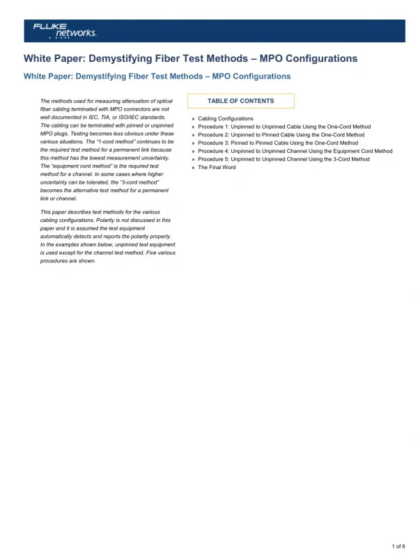
The methods used for measuring attenuation of optical<br>fiber cabling terminated with MPO connectors are not<br>well documented in IEC, TIA, or ISO/IEC standards.<br>The cabling can be terminated with pinned or unpinned<br>MPO plugs. Testing becomes less obvious under these<br>various situations. The “1-cord method” continues to be<br>the required test method for a permanent link because<br>this method has the lowest measurement uncertainty.<br>The “equipment cord method” is the required test<br>method for a channel. In some cases where higher<br>uncertainty can be tolerated, the “3-cord method”<br>becomes the alternative test method for a permanent<br>link or channel.

E N D
White Paper: Demystifying Fiber Test Methods – MPO Configurations White Paper: Demystifying Fiber Test Methods – MPO Configurations TABLE OF CONTENTS The methods used for measuring attenuation of optical fiber cabling terminated with MPO connectors are not well documented in IEC, TIA, or ISO/IEC standards. The cabling can be terminated with pinned or unpinned MPO plugs. Testing becomes less obvious under these various situations. The “1-cord method” continues to be the required test method for a permanent link because this method has the lowest measurement uncertainty. The “equipment cord method” is the required test method for a channel. In some cases where higher uncertainty can be tolerated, the “3-cord method” becomes the alternative test method for a permanent link or channel. » Cabling Configurations » Procedure 1: Unpinned to Unpinned Cable Using the One-Cord Method » Procedure 2: Unpinned to Pinned Cable Using the One-Cord Method » Procedure 3: Pinned to Pinned Cable Using the One-Cord Method » Procedure 4: Unpinned to Unpinned Channel Using the Equipment Cord Method » Procedure 5: Unpinned to Unpinned Channel Using the 3-Cord Method » The Final Word This paper describes test methods for the various cabling configurations. Polarity is not discussed in this paper and it is assumed the test equipment automatically detects and reports the polarity properly. In the examples shown below, unpinned test equipment is used except for the channel test method. Five various procedures are shown. 1 of 6
Cabling Configurations Cabling configurations can take on one of these four forms: unpinned plugs on both ends of the cabling (see Figure 1), unpinned on one end and pinned on the other end of the cabling (see Figure 2), pinned on both ends of the cabling (see Figure 3), unpinned on both ends for a channel (see Figure 4). Figure 1. Unpinned plug on both ends (permanent link) Figure 2. Unpinned plug and pinned plug on ends (permanent link) Figure 3. Pinned plugs on both ends (permanent link) Figure 4. Unpinned plugs on both ends (channel) Note: MPO transceivers are pinned. Equipment cords are unpinned. 2 of 6
Procedure 1: Unpinned to Unpinned Cable Using the One-Cord Method 1. Set a reference between the light source and power meter using the launch cord (see Figure 5). Figure 5. Set the reference 2. Attach the launch cord, power meter, and receive cord to the cabling under test (see Figure 6). Figure 6. Measure attenuation of cabling 3. Make the measurement and compare to the reference measurement. Procedure 2: Unpinned to Pinned Cable Using the One-Cord Method 1. Set a reference between the light source and power meter using the launch cord (see Figure 7). Figure 7. Set the reference 2. Attach the launch cord and receive cord to the cabling under test (see Figure 8). Figure 8. Measure attenuation of cabling 3. Make the measurement and compare to the reference measurement. 3 of 6
Procedure 3: Pinned to Pinned Cable Using the One-Cord Method When using unpinned test equipment for making measurements on pinned to pinned cabling, a mismatch will occur as explained in the procedure below. 1. Set a reference between the light source and power meter using the launch cord (see Figure 9). Figure 9. Set the reference 2. Attach a receive cord to the power meter. 3. Attach the launch cord and receive cord to the cabling under test (see Figure 10). Notice that a pinned to pinned connection mismatch now exists. What to do? Testing a pinned to pinned cabling configuration requires an additional short length test cord (e.g., adapter cord) and a slightly modified reference method. REPEAT TEST – START OVER Figure 10. Measure attenuation of cabling – mismatch 4. Set a reference between the light source and power meter using the launch cord and receive cord (see Figure 11). Figure 11. Set the reference 5. Attach an adapter cord to the launch cord. 6. Attach the launch cord, adapter cord, power meter, and receive cord to the cabling under test (see Figure 12). Figure 12. Measure attenuation of cabling 7. Make the measurement and compare to the reference measurement. 4 of 6
Procedure 4: Unpinned to Unpinned Channel Using the Equipment Cord Method The equipment cord is the patch cord attached to the transceiver during normal transmission. The channel includes the cabling and the two equipment cords. The attenuation includes the connector attenuation at the cabling, the fiber attenuation, but not the connector attenuation that mates to the transceiver. In this example, pinned a LSPM is shown. 1. Set a reference between the light source and power meter using the launch cord and equipment cord (see Figure 13). Figure 13. Set the reference 2. Disconnect the power meter from the equipment cord 1 but not the light source nor the launch cord. 3. Connect the power meter to equipment cord 2. 4. Connect the LSPM, launch cord, and equipment cords (see Figure 14). Figure 14. Measure attenuation of channel 5. Make the measurement and compare to the reference measurement. 5 of 6
Procedure 5: Unpinned to Unpinned Channel Using the 3-Cord Method The “cabling” can represent a permanent link or channel which, in the case of the channel, includes the equipment cords (not shown). 1. Set a reference between the light source and power meter using the launch cord, receive cord, and substitution cord (see Figure 15). Figure 15. Set the reference 2. Replace the substitution cord with the cabling under test using the adapters attached to the cabling (see figure 16). Figure 16. Make the measurement 3. Make the measurement and compare to the reference measurement. The Final Word Refer to the manufacturer’s instruction manual. Fluke Networks operates in more than 50 countries worldwide. To find your local office contact details, go to www.flukenetworks.com/contact. © 2017 Fluke Corporation. Rev: 04/18/2017 7:59 am (Literature Id: 7001797) 6 of 6