Gas Turbine Applications
420 likes | 1.37k Vues
Gas Turbine Applications. LM 2500, Allison 501, The Plant. Objectives. LM 2500 Gas Turbine Engine - specific components, specifications, systems Allison 501 Gas Turbine Generator Set - purpose and operation Interrelationship of supporting systems and operations Engineering plant lineups.

Gas Turbine Applications
E N D
Presentation Transcript
Gas Turbine Applications LM 2500, Allison 501, The Plant
Objectives • LM 2500 Gas Turbine Engine - specific components, specifications, systems • Allison 501 Gas Turbine Generator Set - purpose and operation • Interrelationship of supporting systems and operations • Engineering plant lineups
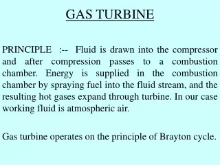
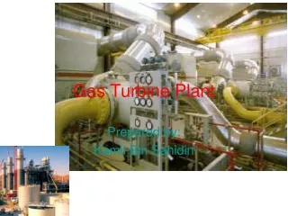
Gas Turbine Power Plants • Power section • Power turbine • Gas generator section • Compressor • Combustion chamber • Gas generator turbine
LM 2500 • In DDG’s and CG’s, have 4 engines • In FFG’s, have 2 engines • Engines are shock mounted to minimize noise and allow for protection • Advantages of LM 2500 • Compact & light • Easy to maintain & repair • Quick start time (~ 1 min)
LM 2500 Components • Starter • Pneumatic - driven by pressurized air • Compressor • 16-stage, axial flow (17:1 compression ratio) • Has some controllable pitch vanes to provide proper air flow and prevent stall
LM 2500 Components • Combustion Chamber • Annular design • 30 fuel nozzles
LM 2500 Components • Gas Generator Turbine • HP Element only • High speed • Power Turbine • Split shaft to allow varying output speeds while maintaining constant generation of energy • 6 sets of nozzles and blades • Lower speed than GGT
LM 2500 Engine Control • Gas Generator Turbine • Produces energy available for power turbine • Controlled by throttles - alters fuel flow • Runs at set continuous RPM • Power Turbine • Speed depends on quantity of exhaust gases from gas generator turbine & propulsion load • Double helical, double reduction, locked train reduction gears
LM 2500 Characteristics • Stage efficiency = 92.5% • R&D: 30,000+ hrs of op-testing • Two versions available: • LM 2500-20 (22,500 shp) • LM 2500-30 (30,000 shp) – USN warships
LM 2500 Engine Control • Speed Governor • Used to prevent power turbine from exceeding speed limit (104%) • Reduces fuel to gas generator section which reduces gases to power turbine • Overspeed Trip • If governor fails, trip secures fuel to LM 2500 to shut it down (108%)
CRP Propeller & Propulsion Shafting • Shaft is hollow to provide flow of oil to propellers • LM 2500 cannot operate at < 5,000 RPM (corresponds to ~11 kts for DDG) • Pitch of blades controlled hydraulically through pistons and gears • Pitch must be adjusted to go slower than 11 kts
CRP Propeller & Propulsion Shafting • In order to go faster than 11 kts, shaft RPM increased • In order to go astern, pitch varied to reverse flow • Overall purpose • Controllable pitch to improve efficiency • Reversible to allow for ahead/astern flow with single direction rotation of shaft
Plant Lineups • Disadvantage of gas turbine • VERY poor partial load fuel economy • LM 2500’s connected to reduction gears via pneumatic clutch • Three possible lineups • Full Power • Split Plant • Trail Shaft
Plant Lineups • Full Power Lineup • 2 turbines/shaft with 2 shafts (4 turbines) • Max speed > 30+ kts • Split Plant Lineup • 1 turbine/shaft with 2 shafts (2 turbines) • Max speed = 30 kts • Trail Shaft Lineup • 1 turbine/shaft with 1 shaft (1 turbine) • Other shaft windmilling • Max speed = 19 kts
Air Intake & Exhaust • Must minimize space and weight • Must keep air inlet losses to a minimum to ensure maximum performance • Intake has screens/filters to ensure clean, filtered air at all times
Air Intake & Exhaust • Exhaust generates thermal and acoustic problems • Possible damage to personnel & equipment • Increased detection & weapons guidance from heat (IR signature) • Silencers and eductor nozzles used to silence and cool exhaust
Allison 501 Gas Turbine Generator Set (GTGS) • Used to generate electricity • Three 2000KW GTGS • Any two can supply electrical needs of ship • Separated by 3 water-tight bulkheads to minimize potential battle damage • Single Shaft • Waste Heat Boiler • Uses heat of exhaust to generate low pressure steam for auxiliary purposes
Safety Features • Automatic Shutdown on: • High Vibration • Cooling System Failure • Module Fire (UV Flame Detection) • High Turbine Inlet Temp • Low Lube Oil Pressure • Power Turbine Overspeed • Battle Override
Introduction • Overall, various different propulsion designs - to choose, must consider: • Operational requirements • Construction requirements • Manpower requirements • Thermodynamic efficiency
Design Considerations • Minimal size and weight • Reliable & easy to maintain • Cost efficiency & budget • Fuel efficiency over wide power range • Shock resistant to handle stress • Quiet & safe • Manpower & training
Conventional Steam Plant • Advantages: • Efficiency @ cruising speeds • Reliability • Good performance @ partial loading • Usefulness for auxiliary functions • Disadvantages • Large & bulky w/ large manpower req’s • Long start-up time • Large fuel storage & low endurance
Nuclear Power Plant • Advantages • Endurance, reliability, speed • No air required for combustion • No NBC warfare problem • Disadvantages • High costs & weight for shielding • Long startup time • Manpower & training requirements • Radiological problems
Diesel Plant • Advantages • High efficiency @ all loads • Low initial cost and specific fuel cost (SFC) • Reliability • Few operators needed • Disadvantages • Capacity limitations & space considerations • High maintenance & overhaul • High lube oil consumption • Noise
Gas Turbine Plant • Advantages • Light weight & compact • Short startup time • Reliable & quiet • High full-load efficiency • Disadvantages • Large quantities of air (NBC problems) • Large fuel storage • Low efficiency @ partial loads
Hybrid Plants • Overall goal: small, more fuel efficient engines for normal ops while retaining ability to shift to high power units when needed • Examples: • CODAG, CODOG: (Diesel and/or GT) • COGAS (RACER): (GT & Steam ) • CODAS: (Diesel & Steam)
Summary • Diesel plant is a hacker! • Most efficient • Easy to construct and operate • Good versatility • Gas Turbine with CRP screws is a winning combo • Efficient and reliable • Good for mass-production “missile sponges”
Summary • Most versatile is nuclear plant • Tremendous endurance overcomes inefficiency • Saves space and energy • If you consider fuel storage for other plants, it is actually lighter & less expensive