HYDROLOGY
HYDROLOGY. Hydrology is a branch of Earth Science. The importance of hydrology in the assessment,<br>development, utilization, and management of the water resources, of any region, is being increasingly realized at all levels.

HYDROLOGY
E N D
Presentation Transcript
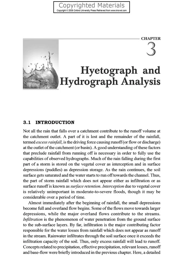
CHAPTER 3 Hyetograph and Hydrograph Analysis 3.1 INTRODUCTION Not all the rain that falls over a catchment contribute to the runoff volume at the catchment outlet. A part of it is lost and the remainder of the rainfall, termed excess rainfall, is the driving force causing runoff (or flow or discharge) at the outlet of the catchment (or basin). A good understanding of these factors that preclude rainfall from running off is necessary in order to fully use the capabilities of observed hydrographs. Much of the rain falling during the first part of a storm is stored on the vegetal cover as interception and in surface depressions (puddles) as depression storage. As the rain continues, the soil surface gets saturated and the water starts to run off towards the channel. Thus, the part of storm rainfall which does not appear either as infiltration or as surface runoff is known as surface retention. Interception due to vegetal cover is relatively unimportant in moderate-to-severe floods, though it may be considerable over a period of time. Almost immediately after the beginning of rainfall, the small depressions become full and overland flow begins. Some of the flows move towards larger depressions, while the major overland flows contribute to the streams. In$ltration is the phenomenon of water penetration from the ground surface to the sub-surface layers. By far, infiltration is the major contributing factor responsible for the water losses from rainfall which does not appear as runoff in the stream. Rainwater infiltrates through the soil surface once it exceeds the infiltration capacity of the soil. Thus, only excess rainfall will lead to runoff Concepts related to precipitation, effective precipitation, relevant losses, runoff and base-flow were briefly introduced in the previous chapter. Here, a detailed
80 Engineering Hydrology coverage of hyetograph and hydrograph is considered with the main objective of estimating runoff, giving equal emphasis to single-storm as well as multiple- storm events. 3 . 2 HYETOGRAPHS The graph that plots the rainfall over the basin along a time scale is called the hyetograph. Although a number of techniques are available for separating the losses from a rainfall hyetograph, the injltrution indices method is the simplest and the most popular technique used for this purpose. In hydrological calculations involving floods, it is convenient to use a constant value of infiltration rate (including all losses from the total rainfall hyetograph) for the duration of the storm. The average infiltration rate is called inJiltration index, and two types of indices are commonly used, they are: (i) &index and (ii) W-index. These indices account for infiltration and other losses. It basically involves a trial and error procedure, which does not differentiate between types of losses, e.g., interception, depression, and infiltration. Certain background on @-index along with its computations has already been provided in the preceding chapter. However, for clarifying distinction between @-index and W-index, both of these are explained below. 3 . 2 . 1 @-Index The @-index or constant loss rate is defined as the rate of rainfall above which the rainfall volume equals the runoff volume (Fig. 3.1). Mathematically, the &index can be expressed as the average rainfall above which the rainfall volume is equal to the direct runoff volume. The @-index is derived from the rainfall Y ,. I 4-index Total losses *x Time (hr) Fig. 3 . 1 A generalized rainfall hyetograph showing $-index in relation to total rainfall
Hyetograph and Hydrograph Analysis 81 hyetograph which also helps to calculate the direct runoff volume. The @-value is found by treating it as a constant infiltration capacity. If the rainfall intensity is less than @ , then the infiltration rate is equal to the rainfall intensity. However, if the rainfall intensity is greater than @ , then the difference between rainfall and infiltration in an interval of time represents the direct runoff volume. The amount of rainfall in excess of the index is called excess rainfall. The @-index thus accounts for the abstraction of total losses and enables runoff magnitudes to be estimated for a given rainfall hyetograph. The example given below illustrates the calculation of @-index. Mathematically, the @-index can be expressed as: P-R @= 1 1, where, P = total storm precipitation (mm or cm) R = total direct surface runoff (mm or cm) t,= duration of the excess rainfall, ie., the total time in which the total intensity is greater than @ (in hours), and (3.la) @ = uniform rate of infiltration ( d h r or cm/hr) If antecedent precipitation conditions in the catchment is such that other losses due to interception, depression, and evaporation, etc. are considerable in the beginning of the storm, then these losses may have to be subtracted from the rainfall, before applying the uniform loss rate method (@-index) for computing the excess rainfall. Since infiltration accounts for majority of the water losses in heavy storms, the @-index method must be interpreted for all practical purposes as a constant infiltration capacity method. It is a well-known fact that the infiltration capacity decreases with time. Therefore, the @-index method is not that realistic due to varying infiltration capacity with time. It underestimates the infiltration for early rainfall and overestimates it for later rainfall. In addition, one does not know how to extrapolate the @-value determined for one storm to another storm. In spite of these drawbacks, this simple method is often used for computing the excess rainfall hyetograph. The derivation of @-index is simple, and the approach is described below with the help of two examples. Example 3.1 A storm with 10 cm precipitation produced a direct surface runoff of 5.8 cm in the equivalent depth unit. The time distribution of the storm is given in Table 3.l(a). Estimate the @-index of the storm and the excess rainfall hyetograph. Table 3.l(a) Time from start (hr) Incremental rainfall in each hour (cm) 1 2 3 4 5 6 7 8 0.4 0.9 1.5 2.3 1.8 1.6 1.0 0.5
82 Engineering Hydrology Solution Compute total infiltration, i.e., Total infiltration = Total rainfall - Direct surface runoff = 10 - 5.8 = 4.2 cm Assume duration of the excess rainfall (t,) is equal to the total duration of the storm for the first trial, i.e., t, = 8 hr Compute the trial value of @ as: Compare the above @ value with individual blocks of rainfall. The @ value makes the rainfall of the first hour and the eighth hour ineffective as their magnitudes are less than 0.525 cdhr. Therefore, value oft, is modified. Assume t, = 6 hour in the second trial and modified value of total rainfall for 6 hour duration will be 10 Compute a modified value of infiltration, i.e., infiltration = 9.1 ~ 5.8 = 3.3 cm Compute second trial value of @ , i.e., @ = 3.3/6= 0.55 cmlhr. This value of @ is satisfactory as it gives t, = 6 hr Calculate the excess rainfall, subtracting the uniform loss fiom each block. The excess rainfall hyetograph is given below: ~ (0.4 + 0.5) = 9.1 cm Table 3.l(b) Calculation of excess rainfall Time from start (hr) Excess rainfall (cm) 1 0 2 3 4 5 6 7 8 0 0.35 0.95 1.75 1.25 1.05 0.45 Note that the total excess rainfall = 5.8 cm = direct surface runoff (cm) Example 3.2 A storm with 12.0 cm precipitation produced a direct runoff of 6.8 cm. The time distribution of the storm is given in Table 3.2(a). Estimate @-index. Time from start (hr) Incremental rainfall in each hour (cm) 1 2 3 4 5 6 7 8 0.56 0.95 1.9 2.8 2.0 1.8 1.2 0.61 Solution Total infiltration = 12.0 - 6.8 = 5.2 cm Assume t, = duration of excess rainfall = 8 hr for the first trial. Then, @ = 5.218 = 0.65 c& But, this value of @ makes the rainfalls of the first hour and the eighth hour ineffective as their magnitude is less than 0.65 c&. required to be modified. Hence, the value oft, is
Hyetograph and Hydrograph Analysis 83 Assume t, = 6 hr for the second trial. In this period: Infiltration = 12.0 - (0.56 + 061 + 6.8) = 4.03 $ = 4.03/6 = 0.67 cdhr This value of $ is satisfactory as it gives t, = 6 hr. Table 3.2(b) Calculation of excess rainfall 6 Time from start (hr) Excessrainfall(cm) 8 0 4 5 3 7 1 0 2 0.28 1.23 2.13 1.33 1.13 0.53 Total excess rainfall = 6.8 cm =total runoff. 3 . 2 . 2 W-Index In an attempt to refine the $-index, the initial losses are separated from the total abstractions and an average value of infiltration rate (called the W-index) is calculated as given below: W=(P-R-I,)/t, where P = total storm precipitation (cm) R = total storm runoff (cm) I, = initial losses (cm) t, = duration of the excess rainfall (in hours), i.e., the total time in which the rainfall intensity is greater than inJiltration capacity and (3.lb) W = average rate of infiltration (cm/hr) Example 3.3 Determine $-index and W-index for a watershed SW-12 with an area of 100 km2. A rainfall with the specifications given in the following table occurred in the watershed. 0.300 The average flow measured at the outlet of the watershed was 100 m3/s. Assume the retention to be 10% of rainfall. Solution Total rainfall P = 0.150 + 1.205 + 0.75 = 2.105 cm Totalrunoff Q=(100m3/s) x(15Ox6Os)/(1OOx 106m2)=0.009m=0.9cm Total loss = 2.105 - 0.9 = 1.205 cm Total time T = 150/60 = 2.5 hr
84 Engineering Hydrology The estimated value of 4 is = 1.205/2.5 = 0.482 Consider @initial = 0.7 cm /hr Net rainfall is obtained as follows: Table 3.3 Calculation of excess rainfall Net rainfall i n cm [ ( I ) - (2)] x (duration o f rainfall i n hr) I I I I I I 0.3 1.205 0.7 0.7 0 0.505 I 0.7 0.4 1.500 This shows that 4 = 0.7 cdhr is acceptable. AS W=(P-R-I,)It, 2.105 - 0.9 - (0.2 x 2.105) = 0.52 cm/hr Tndex = 1.5 In the calculation, 20% of rainfall is taken as initial losses. 3 . 3 HYDROGRAPHS Design of structures, e.g., determining the height of a dam, spillway design, design of bridge culverts, sizing the capacity of outlet works, etc., require information about extreme magnitudes of floods. It requires quantitative information on both peak flows and time distribution of runoff or hydrographs. Thus, a hydrograph gives the temporal variation of flow at the outlet of the catchment or basin. The flow may be expressed in different units, e.g., in terms of discharge [L3/T], or depth of flow per unit time [L/T]. The hydrograph yields time distribution of runoff from the excess rainfall occurring over a catchment for any given event. The runoff is generally measured at a gauging site located at the outlet of a catchment. In India, systematic gauging records are maintained by Central Water Commission and different state agencies for most of the major and medium basins. The unit hydrograph theory proposed by Sherman (1 932) is primarily based on principle of linearity and time and space invariance. For the gauged catchments, unit hydrographs can be derived from the analysis of available rainfall-runoff records. The procedures used to derive a unit hydrograph depend on the type of storm, whether it is a single-period storm or a multi-period storm. Thunderstorms, generally being intense and of short duration, are treated as single-period storms. On the other hand, frontal storms of usually longer duration are treated as multi-period storms. A unit hydrograph converts the rainfall (excess rainfall) to runoff (direct surface runoff). For its derivation, the duration of the unit hydrograph is
Hyetograph and Hydrograph Analysis 85 generally taken as the duration of excess rainfall block. However, S-curve and superimposition methods can be utilized for deriving a unit hydrograph of desired duration. The former approach is more general than the latter, because the former approach changes the duration of available unit hydrograph to any duration length. This chapter includes description of unit hydrograph theory, its assumptions, and limitations; derivation of unit hydrograph and factors influencing its derivation, instantaneous unit hydrograph (IUH), S-curve, change of unit hydrograph duration, and derivation of average unit hydrograph. The unit hydrograph derived from an event usually differs from another unit hydrograph derived from a different event. There are two possible approaches available for the derivation of the representative unit hydrograph for a watershed. The first approach averages the unit hydrographs derived for various events using conventional arithmetic averaging. The second approach, however, accumulates various events as a collective unit and then derives a representative single unit hydrograph for the watershed. 3.3.1 Definition of Unit Hydrograph A unit hydrograph (UH) is a hydrograph of direct surface runoff from a unit excess rainfall occurring in unit time uniformly over the catchment area. The excess rainfall (ER) excludes losses, i.e., hydrological abstractions, infiltration losses from total rainfall; and unit excess rainfall volume equalling 1 mm may be considered as a standard value since rainfall is usually measured in mm. However, in certain cases, UH is derived for 1 cm ER. The selection of unit time depends on the duration of storm and size of the catchment area. For example, for small catchments, periods of 1 or 2 hours can be assumed; and for larger catchments, 3,4, 6, or even 12 hours can be adopted. A unit hydrograph can be interpreted as a multiplier that converts excess rainfall to direct surface runoff. The direct surface runoff (DSRO) is the streamflow hydrograph excluding base-flow contribution. Since, a unit hydrograph depicts the time distribution of flows, its multiplying effect varies with time. In real-world application, the unit hydrograph is applied to each block of excess rainfall; and the resulting hydrographs from each block are added for computing direct surface runoff hydrographs, to which base-flows are fwther added to obtain total flood hydrographs. 3.3.2 Unit Hydrograph Theory and Assumptions The unit hydrograph theory can be described using the following underlying assumptions: Constant Base Length Assumption The base of direct surface runoff (tB) corresponding to a rainfall amount of a given duration (7') is constant for a catchment and does not depend on the total
86 Engineering Hydrology runoff volume. For example, if T is the duration of excess rainfall, the base length of the DSRO for all rainfall events of this duration is the same for all events and is equal to tB, as shown in Fig. 3.1. Proportional Ordinate Assumption For storms of same duration, the ordinate of DSRO at a time, i.e., Q(t) is proportional to the total volume of excess rainfall. Thus, Ql(t) = k PE1 and Q2(t) = k PE2, where Qi(t) is the ordinate of DSRO at any given time t for the ith storm having an excess rainfall volume of PEi, and k is proportionality constant. Similarly, the excess rainfall of another event, PE3, over a time period T is equal to Pm T. Therefore, at a given time t, the following proportionality holds. Figure 3.2 shows the surface runoff hydrographs for three different excess rainfall volumes of 10, 20, and 30 mm for the same unit period. The ratio of qlO:q20:q30 = 10:20:30 = 1:2:3. Thus, the ordinates of the DSRO produced by 60 mm excess rainfall will be 0.6 times the available 100 mm unit hydrograph. ' T T T '\ ', '\. /' ,/' Fig. 3.2(a) Three different unit hydrographs with the same base but varying peaks Concurrent Flow Assumption The hydrograph of surface runoff that results from a particular portion of storm rainfall is not affected by the concurrent runoff resulting from other portions of the storm. In other words, the total hydrograph of surface runoff is the surn of the surface runoff produced by the individual portions of the excess rainfall. Figure 3.3 shows two hydrographs: one resulting from excess rainfall PE1 and another from the excess rainfall PE2. The DSRO (Q,) from the first excess rainfall (PE1) is not affected by the DSRO (Q2) from the second excess rainfall (PE2). The total DSRO is, therefore, the surn of Q, and Q2.
Hyetograph and Hydrograph Analysis 87 /-, Q30 /' ' \ Fig. 3.2(b) Surface runoff hydrographs for three different excess rainfall volumes of same unit period Fig. 3.3 The total hydrograph resultingfiom consecutive storms Uniform Excess Rainfall in Time Assumption It is assumed that the excess rainfall is the result of constant intensity of excess rainfall, which is equal to the excess rainfall divided by time duration T. The assumption requires that: (i) the selected storm must be intense and of short duration, and (ii) the resulting hydrograph be of short time base and single peaked. Uniform Excess Rainfall in Space Assumption It is assumed that the intensity of excess rainfall is uniform over the whole catchment. For the validity of this assumption, the catchment considered should
88 Engineering Hydrology be small. Therefore, the unit hydrograph theory is not applicable to large watersheds (more than 5000 sq. km). It can, however, be applied in components by subdividing the large watersheds. Time Invariance Assumption It is assumed that the unit hydrograph derived for a watershed does not vary with time. This principle holds when: (i) the physical characteristics of the watershed do not change with time and (ii) storm pattern and its movement do not change with time. 3.3.3 Factors Affecting Unit Hydrograph Shape The factors affecting the shape of unit hydrograph are the rainfall distribution over the catchment and physiographic elements of the catchment, viz., shape, slope, vegetation, soil type, etc. Rain f a 11 Distribution A variation in the areal pattern of rainfall, rainfall duration, and time intensity pattern greatly affects the shape of the hydrograph. For example, a hydrograph resulting from a rainfall concentrated in the lower part of a basin, i.e., nearer to the outlet of the basin (gauging site) will have a rapid rise since most of the rainfall volume will reach the outlet in a short time. This yields a sharp peak and a rapid recession. On the other hand, rainfall concentrated in the upper part of the same basin will yield a slow rising and receding hydrograph having a broad peak. Therefore, it is natural that unit hydrographs developed from rainfall of different areal distributions will exhibit differing shapes. This is one reason why the unit hydrograph technique is restricted to small basins. Small basins generally have a uniform structure throughout, which reduces the difference between the shapes of two unit hydrographs of equal excess rainfalls having same duration but different areal extensions. For a given amount of runoff, the time base of the unit hydrograph increases and the peak lowers as the duration of rainfall increases. This means that two rainfall events having different intensities yield two different shapes of hydrographs. On large basins, changes in storm intensity should last for several hours to produce distinguishable effects on the hydrograph. The storage capacity of large basins tends to eliminate the effects of short time intensities and only major variations in the time intensity pattern is reflected in the hydrograph. On the other hand, on small basins, short bursts of excess rainfall lasting only for a few minutes may yield clearly defined peaks in the hydrographs. Thus, the effects of variation in the time intensity pattern can be lessened by selecting a short computational interval so that the variation in patterns from one computational interval to the next is not significant.
Hyetograph and Hydrograph Analysis 89 Physiography o f the Catchment Physical characteristics of a watershed change with time due to man-made interfaces, change in vegetative cover, and degradation of soil surface due to changing physiographical effects. Due to this, the shape of the derived unit hydrograph also changes. Due to high velocity of flow, steep catchment slopes produce runoff peaks earlier than flatter slopes; consequently, giving rise to earlier hydrograph peaks than that of flatter slopes. Seasonal and long-term changes in vegetation or other causes, such as fire, also change the physical characteristics of the watershed. It resorts to developing a regional relationship between unit hydrograph parameters and existing basin characteristics, for deriving the unit hydrograph in the changed environment. 3.3.4 Base-flow Separation The main objective while deriving a unit hydrograph (hereafter, we shall refer it as UH) is to establish a relationship between surface flow hydrographs and the effective rainfall. In other words, the response of the basin to any input such as rainfall (in this case) is established using the available rainfall-runoff (discharge) data. The surface flow hydrograph is obtained from the total storm hydrograph by separating the quick-response flow from the slow-response runoff. There are three methods available to separate the base flow. Some of these methods have already been introduced in the previous chapter. Method I This is the simplest method and is generally practiced by field engineers. In this method, the base-flow is separated by drawing a straight line from the beginning of the surface runoff to a point on the recession limb representing the end of direct runoff. In Fig. 3.4, point A represents the end of direct runoff, identified by the sharp end of direct runoff at that point; and point B marks the end of direct runoff. An empirical equation for the time interval of N days from the peak to the point B is given by: N = 0.83 (3-3) where, A = drainage area in km2, and N in days The value of N is approximate, and position of B should be decided by considering the number of hydrographs. Method 1 1 In this method, base-flow existing prior to the commencement of the surface runoff is extended until it intersects with the ordinate drawn at the peak point C. This point is joined to point B by a straight line. The segments AC and CB demarcate the base-flow and surface runoff. This method is most widely used in engineering practises. Method 111 In this method, the base-flow recession curve, after depletion of flood water, is extended backwards till it intersects with the ordinate at the point of inflection
90 Engineering Hydrology Fig. 3.4(a) Schematic diagram showing various salient points used for base-flow separation (line EF in Fig. 3.4(a)). This method is realistic in situations where groundwater contributions are significant and reach the stream quickly. All the above methods of base-flow separation are arbitrary, and the selection of any of these methods is dependant on local practise and successful predictions achieved in the past. Example 3.4 having an area of 450 km2 are given below: The ordinates of discharge for a typical storm of a catchment Table 3.4(a) Ordinates of discharge Erne (hrs) 0 6 12 18 24 30 Discharge (rn3/s) 12 15 25 75 120 110 Erne Discharge (rn3/s) 90 75 63 45 35 30 Erne Discharge (m3/s) 27 22 15 13 13 13 36 42 48 54 60 66 72 78 84 90 96 102 Find ordinates of the direct surface runoff hydrograph using straight-line technique for base-flow separation. Solution The computational steps involved are: (i) Plot the recession limb of the discharge hydrograph on a semilog graph paper, keeping time on arithmetic scale and discharge values on log scale.
Hyetograph and Hydrograph Analysis 91 (ii) Locate the recession point in the above plot. (iii) Draw a straight line from the rising point of the hydrograph to the recession limb of the hydrograph for base-flow separation. (iv) Subtract the base-flow ordinates from the corresponding discharge hydrograph ordinates to estimate direct surface runoff hydrograph ordinates. Table 3.4(b) shows the above computations. Here the base-flow ordinates, given in column (3) are subtracted from the discharge hydrograph ordinates, given in column (2). The resulting hydrograph ordinates known as direct surface runoff hydrograph ordinates are given in column (4). It can be seen from the above plotted hydrograph (Fig. 3.4(b)) that the storm hydrograph has a base-flow component. Using the straight line technique for base-flow separation, we can find the time interval (N days) from the peak to the point B. 0 1 0 I 60 80 100 120 20 40 Time (hr) Fig. 3.4(b) Baseflow separation Using Eq. (3.3): N = 0.83 = 2.8165 days = 67.6 hrs N can be calculated by judgement. Beginning of DRH End of DRH Peak Hence, N = 90 -24 = 66 hr For convenience, N is taken as 66 hrs. A straight line is drawn between the t = 0 t=90hr t=24hr points A and B which demarcates the base-flow and surface runoff
92 Engineering Hydrology Table 3.4(b) Estimation of direct surface runoff Base--ow (m 3 4 ) (3) 12 12 12 12 12 12.5 12.5 12.5 12.5 12.5 12.5 12.5 13 13 13 13 13 13 Direct Surface Runoff (m3/s) (4) = (2) - (3) 0 3 13 63 108 97.5 77.5 62.5 50.5 32.5 22.5 17.5 14 9 2 0 0 0 7ime (he) (1) 0 6 12 18 24 30 36 42 48 54 60 66 72 78 84 90 96 102 Dischavge Hydrograph (m 3 4 ) (2. 12 15 25 75 120 110 90 75 63 45 35 30 27 22 15.0 13 13 13 Example 3 . 5 The ordinates for discharge of a typical storm fiom a catchment having an area of 50 km2 are given below. Estimate the direct surface runoff and the volume of excess rainfall for the given event. Table 3.5(a) Estimation of direct surface runoff Q (rn3/s) dQ/dt (2) t (hrs.) Q (rn3/s) dQ/dt (1) (2) t (hrs.) (1) t (hrs.) (2) t (hrs.) (1) dQ/dt (3) (3) (3) 0 1 2 3 4 5 6 7 8 9 61.67 63.67 64.5 88.74 24 25 26 27 28 29 378 356 341.75 344.42 339.1 296.8 -20 -22 -14.25 2.67 -5.32 42.3 49 50 51 52 53 54 138.88 -13.34 134.04 -12.92 120.6 122.1 99.01 98.11 -23.09 2 0.83 24.24 4.84 -13.44 1.5 ~~ ~~~~ ~~ ~~~~ 103.04 146.04 189.53 224.56 292.8 389.3 14.3 43 43.49 35.03 68.24 96.5 -- ~~ ~~~~ ~~ ~~~~ 30 31 32 33 289.8 280.03 280.03 284.87 -7 -9.77 0 4.84 55 56 57 58 96.55 95.63 94.4 94.4 -0.9 -1.56 -0.92 -1.23 ~~ ~~~~ ~~ ~~~~ ~~ ~~~~ (Contd.)
Hyetograph and Hydrograph Analysis 93 -- 34 243.9 40.97 30.6 2.9 57.6 36 214 -2.03 37 211.95 -2.05 137.2 24.27 38 210 -1.95 -72.87 39 198.17 -11.83 40 196.51 -1.66 -55 -27 41 194.6 -1.91 462.85 -24.15 42 190.3 450 -12.85 43 187.1 425.1 -24.9 422.2 -2.9 412 -10.2 398 -14 47 165.14 48 152.22 -12.92 (Contd.) 10 11 12 13 14 15 16 17 18 19 20 21 22 23 0 419.9 422.8 480.4 617.6 641.87 569 514 487 59 60 88.75 88.7 ~~ ~~~~ 35 216.03 -27.87 -5.65 ~~ ~~~~ 61 62 63 64 65 66 67 68 69 70 71 72 89.91 89.91 87.56 86.75 85.0 83.8 82.7 82.7 82.7 81.61 73.83 71.83 -0.05 1.21 0 -2.35 -3.81 0.05 0 -1.1 0 0 -1.09 -7.78 ~~ ~~~~ ~~ ~~~~ ~~ ~~~~ ~~ ~~~~ ~~ ~~~~ ~~ ~~~~ 4 . 3 -3.2 -9.99 -5.37 -6.34 -0.26 ~~ ~~~~ ~~ ~~~~ 44 45 46 177.11 171.74 165.4 ~~ ~~~~ ~~ ~~~~ ~~ ~~~~ ~~ ~~~~ Solution The flood hydrograph for the above data is shown in Fig. 3.5. The peak of the hydrograph is at t = 14 hours and the peak discharge (Q,) is equal to 641.87 m3/s. Column (3) shows the variation of slope of the hydrograph at different time ordinates. This is used to mark the point of inflection (Pi), change of hydrograph slope. dQldt changes from -24.9 to -2.9 at t = 20 hours. . v which marks the 700 G ' 600 " 8 500 400 3 300 $ 200 b 100 a 0 I 1 80 0 5 10 15 20 25 30 35 40 45 50 55 60 65 70 75 Time (hr) Fig. 3.5 Flood hydrograph This is taken as the point of inflection. Using Eq. (3.3), N = 0.82 x 50°.2 = 1.81 days Therefore, point B (refer Fig. 3.5) is at t = 66 hours. The corresponding discharge at point B is 83.5 m3/s (marked bold in table). From the data, it can be seen that point A falls nearly at 3 hours. The ordinate of direct surface runoff hydrograph using the straight-line technique is given in Table 3.5(b).
94 Engineering Hydrology t t t t t t DSRO DSRO DSRO Q Q Q Q Q Q DSRO (m3/s) (m3/s) DSRO (m3/s) (m3/s) DSRO (m3/s) (m3/s) (m3/s) (m3/s) 61.67 - 63.67 - 64.5 88.74 103.04 146.04 189.53 105.7 224.56 140.8 292.8 389.3 419.9 422.8 480.4 617.6 641.87 558.1 569 514 487 462.85 379.1 450 425.1 422.2 412 398 (m3/s) (m3/s) 378 356 341.75 258 344.42 260.6 339.1 296.8 289.8 280.03 280.03 284.87 243.9 216.03 214 211.95 210 198.17 196.51 194.6 190.3 187.1 177.11 171.74 165.4 165.14 152.22 (m3/s) (m3/s) (hvs.) (hvs.) 24 25 26 27 28 29 30 31 32 33 34 35 36 37 38 39 40 41 42 43 44 45 46 47 48 (hvs.) (hvs.) (hvs.) 0 1 2 3 (hvs.) 0 1 2 3 4 4 5 6 7 8 9 10 11 12 13 14 15 16 17 18 19 20 21 22 23 ~~~~~~~~~ 61.67 - 63.67 I - I 64.5 I - I 88.74 I I 103.04 I 19.24 I 24 25 26 27 28 378 294.2 I 272.2 I 272.2 49 50 51 52 53 53 54 55 56 57 58 59 60 61 62 63 64 65 66 67 68 69 70 71 72 138.88 I 134.04 I 55.08 I 120.6 I 50.24 I 122.1 I 36.8 I 99.01 98.11 96.55 95.63 94.4 94.4 88.75 88.7 89.91 89.91 87.56 86.75 85.0 83.8 82.7 82.7 82.7 81.61 73.83 71.83 68 68 55.08 50.24 36.8 38.3 15.21 14.31 12.75 11.83 10.6 10.6 4.95 4.9 6.11 6.11 2.95 1.2 0 294.2 49 50 51 52 138.88 134.04 120.6 122.1 I I I I 356 I 341.75 I 258 I 344.42 I 260.6 I I 339.1 I 255.3 I ~~~~~~~~~ I ~~~~~~~~~ - 4.94 I 4.94 19.24 ~~~~~~~~~ 99.01 I 38.3 ~~~~~~~~~ 255.3 213 206 196.2 196.2 ~~~~~~~~~ 5 6 7 8 9 146.04 189.53 105.7 224.56 140.8 292.8 389.3 62.24 62.24 29 30 31 32 33 296.8 289.8 280.03 280.03 284.87 213 206 196.2 196.2 201.1 201.1 160.1 132.2 130.2 128.2 126.2 114.4 112.7 110.8 106.5 103.3 93.31 87.94 81.6 81.34 74.88 54 55 56 57 58 98.11 96.55 95.63 94.4 94.4 15.21 14.31 12.75 11.83 10.6 ~~~~~~~~~ ~~~~~~~~~ ~~~~~~~~~ 209 305.5 305.5 336.1 339 396.6 533.8 209 ~~~~~~~~~ ~~~~~~~~~ ~~~~~~~~~ ~~~~~~~~~ ~~~~~~~~~ ~~~~~~~~~ ~~~~~~~~~ 485.2 430.2 403.2 ~~~~~~~~~ ~~~~~~~~~ ~~~~~~~~~ ~~~~~~~~~ 366.2 341.3 338.4 328.2 314.2 ~~~~~~~~~ ~~~~~~~~~ ~~~~~~~~~ ~~~~~~~~~ ~~~~~~~~~ The summation of the DSRO is 10669 m3/s or 10669 x 3600 m3/hr. In terms of depth, this is equal to (10669 x 3600)/(50 x lo6) = 0.000213 m = 0.213 1 1 1 1 1 1 . This is the excess rainfall depth. 3.3.5 Features of UH and Distribution Graph The distribution graph is a non-dimensional form of the unit hydrograph, generally available in percent form. The sum of all percentage values should be equal to 100. The main features of a unit hydrograph or a distribution graph are: It shows the time distribution of the discharge hydrograph of a watershed produced by a uniform excess rainfall of given depth.
Hyetograph and Hydrograph Analysis 95 0 It transforms the excess rainfall to time-varying discharge at the outlet assuming a linear process. 0 It represents the watershed characteristics by exhibiting the integrated effect of the surface features on the routing of the excess rainfall through the catchment. It is worth mentioning that the derivation of a unit hydrograph usually excludes records of moderate floods; and the principles of unit hydrograph can be applied for estimating the design flood, supplementing missing flood records, and short-term flood forecasting that is based on recorded rainfall. 3.4 DERIVATION OF UH Unit hydrograph is extensively used in computation of surface runoffs resulting due to storm events. Similarly, for known direct runoffs and storm characteristics including magnitude and duration, unit hydrograph can be derived. In this section, we discuss the procedures to derive the unit hydrograph. Conventional Method using Single-Peak Storm 3.4.1 The unit hydrograph for a gauging station is derived from a single-period storm as follows: (i) Extract hydrographs for major floods from stream-flow records using observed gauge-discharge or rating curves. (ii) Separate base-flow from total hydrograph to produce direct surface runoff hydrograph. Compute the surface runoff volume Q in mm. In practice, floods of runoff volume greater than 20 mm are analysed. If records of higher floods are not available, lower flow values can also be used, but with caution. (iii) Examine the rainfall records available for the rain gauge stations in the catchment and compute average rainfall for the storm under investigation. (iv) Derive the hydrograph and the total average rainfall for the time period which corresponds to the desired unit period of the unit hydrograph. (v) Determine the loss rate subtracting the direct surface runoff from the total rainfall to estimate the excess rainfall in each of the unit periods. (vi) Since the unit hydrograph is a multiplying factor to convert excess rainfall to DSRO, the procedure for its derivation is as follows: 0 Plot the surface runoff hydrograph. 0 Determine the volume of excess rainfall, PE, in the single unit period. (PE also equals the volume of the direct surface runoff hydrograph QJ . 0 Relate the value of PE to the unit volume of the unit hydrograph, QvH, as demonstrated in the following example.
96 Engineering Hydrology It is important to understand precisely the term “unit volume of the unit hydrograph”. Normally, many textbooks use the word “unit hydrograph” to imply that it is due to 1 cm effective rainfall. This may not always hold good. Unit hydrograph may also imply that it is due to 1 rnm effective rainfall, or for that matter, any other unit, say 1 feet, 1 inch, etc. In this book, we use unit hydrograph in the sense that it is due to 1 rnm effective rainfall. If 1 mrn effective rainfall occurs uniformly over a catchment for a unit time, the volume of UH will be equal to (1 mm x area of catchment). If we divide this volume by the catchment area A, this will be just equal to 1 rnm (the unit used for effective or excess rainfall). Thus, the term “unit volume of unit hydrograph” implies that the volume under the UH is equal to one unit used for effective rainfall of one unit. Example 3.6 to derive a unit hydrograph for 10 mm unit volume. For a given PE of 22.5 111111, obtain proportionality factor (F) Solution Give unit volume of unit hydrograph QUH = 10 1 1 1 1 1 1 , the proportionality factor F can be computed as: Ordinates of the UH can be obtained by dividing the direct surface runoff hydrographs by F. Please note that unit volume of such UH will be equal 10 mm. Example 3.7 154 mm produces the following surface runoff hydrograph: A thunderstorm of 6-hr duration with the excess rainfall of Table 3.6(a) Data for Example 3.7 June 15 June 16 June 17 Date Time (Hrs) DSRO (m3/s) 0600 1200 1800 M.N. 0600 1200 1800 M.N. 0600 1200 1800 M.N. 0 0 0 10 500 1600 3500 5200 3100 1500 650 250 Find the ordinates of a 6-hr UH of unit volume equal to 100 1 1 1 1 1 1 . Solution Since PE = 154 = 1.54. The ordinates of unit hydrograph are computed dividing the direct surface runoff hydrograph ordinates by the conversion factor. The calculation of 6-hr unit hydrograph for the above storm is shown in Table 3.6(b). and QvH = 100 1 1 1 1 1 1 , the conversion factor F = 154l100
Hyetograph and Hydrograph Analysis 97 Table 3.6(b) Computation of 6-hr unit hydrograph 6-hv 100 mm unit hydvogvaph (m3/s) Date runoff June 15 1800 2400 0600 1200 1600 3500 5200 3100 1500 650 1039 2272 3377 2013 974 422 I I June 16 I I 2400 0600 1200 1800 250 162 June 17 0 0 0 0 3.4.2 UH Derivation from a Multi-period Storm When a storm is of short duration and of fairly uniform intensity, the unit hydrograph can be derived by simply applying the single period storm technique. However, for a storm of long duration or a shorter one with variable intensity, the storm should be treated as consisting of a series of storms and the derivation of the unit hydrograph gets slightly more complicated. There are a number of methods to derive unit hydrographs from multi-period storms, but all are based on unit hydrograph theory as follows. Let Pei = intensity of excess rainfall (mm/hr), PEi = volume of excess rainfall (mm), Ui = ordinates of unit hydrograph (m3/sec), Qi surface runoff hydrograph (m3/sec), and i = an integer value for an ordinate. The underlying procedure of calculating the direct surface runoff hydrograph from a multi-period storm is described below. If Pei = rainfall rate ( d h r ) in period T, then PEi = volume of rainfall = Pei x T. For example, if Pei = 2 mm/hr and T = 2 hr, then PEi = 2 x 2 = 4 mm. To determine the direct surface runoff hydrograph fiom 4 mm of rainfall that occurred in 2 hrs, the 10 mm unit hydrograph of 2-hr duration having 7 unit periods (time base = 7 x 2 = 14 hrs) is used. Thus, = ordinates of direct (i) the base length of the direct surface runoff hydrograph for rainfalls in excess of 2-hr duration is 14 hr (ii) for a 10 mm unit hydrograph, the average runoff in the various periods for the first rainfall in excess of 4 mm is computed using the proportionality principle, as given below:
98 Engineering Hydrology Q7 = 0.4 x U7 Q, = 0.4 x U, Q3 = 0.4 x U3 Qs = 0.4 x Us Q2 = 0.4 X U2 Q4 = 0.4 X U4 Q6 = 0.4 X U6 (iii) If PE2 = 4 d h r (2nd period of rainfall) or PE2 = 4 X 2 = 8 1 1 1 1 1 1 , the ordinates for the second period of rainfall will be as follows: Q2 = 0.8 x U2, Q, = 0.8 x U,, and so on. It is to be noted that the excess rainfall in the second period is lagged by T = 2 hr. Thus, Q, of the second period of rainfall is added to the second period of runoff for first hydrograph ordinate. This principle continues for the third and subsequent rainfall values. The equations for the combined surface runoff can, therefore, be generalised as follows: Qi =PEI ui Q2 = PEI u 2 + pE2 ui Q3 =PEI u 3 +PE2 u 2 +Pm ui Q4 = PEI u 4 + pE2 u3 + 'E3 u2 Q5 = PEI u 5 + pE2 u4 + 'E3 u3 Qs = p u6 + pE2 us + 'E3 u4 ~ l Q7 = pE1 u 7 + pE2 u6 + 'E3 Q,=O+PBU~+PE~U~ Q, = O+ O +PE3 U 7 All the following procedures used for deriving unit hydrographs from multi- period storms use the principles of proportionality and superposition. Method o f Single Division This is basically a trial and error approach. The following procedure involves solving each of the above equations relating to the unit hydrograph ordinates, as shown in Fig. 3.6. For the first rainfall, both Q, and PEl are known; Q, from the surface runoff hydrograph and PE1 from the hyetograph excess rainfall. Thus, Q, =PE1 X u, or u 1 = ~ Qi pE 1 For the second rainfall, Q2 is known from the hydrograph; and PE1, U,, and PB are already known. Thus, the unit hydrograph ordinates (q. ) are computed.
Hyetograph and Hydrograph Analysis 99 Fig. 3 . 6 Unit hydrograph derivation from a multiperiod storm Since there are more equations than unknown values, the equations relating Q, and Q, to u 6 and U,, respectively, may not be in balance. Therefore, it is necessary to apply an ‘averaging’ procedure. It involves calculation of U,, U2 ,..., U, from Q,, Q2 ,..., Q7 (forward run); and the calculation of U,, u 6 ,..., U1 from Q,, Q,, ...,Q, (backward run) as illustrated in Fig. 3.6 through a typical example. The unit hydrograph ordinates are then derived by ‘averaging’ the values of U,, U,, ..., U, computed from the two runs. The derived unit hydrograph is then checked for producing a hydrograph that compares well with the recorded hydrograph. This test is recommended in all unit hydrograph derivations. The direct surface runoff hydrograph computed using the above average unit hydrograph does not match satisfactorily with the observed direct surface runoff hydrograph. This deviation may be attributed to small errors in U,, U,, u 6 , and U,, which are the leading and trailing ordinates, respectively; and these values propagate in calculations of other ordinates. Computations rely more on U, and U, in forward run and U, and U, in backward run. Furthermore, it is possible that (i) the records of rainfall and runoff may not be representative for the actual situation, (ii) the unit hydrograph theory may not be applicable to the storm, and (iii) storms may not be uniformly distributed over the catchment. These circumstances create difficulties in derivation of unit hydrograph.
100 Engineering Hydrology Least Squares Method As is evident in single division method, there are more equations than unknown values and the solution adopted depends on the selected set of equations. The least squares method is a statistical curve fitting procedure which yields a ‘line of best fit’. The basic principle of the least squares method lies in the fact that the line of best fit produces the best reproduction of the hydrograph, computed from the application of the unit hydrograph to the excess rainfall, as shown in Fig. 3.7. The developed unit hydrograph yields minimum deviation of the ordinates of the reproduced hydrograph from the ordinates of the actual hydrograph. Fig. 3 . 7 Goodness-of-fit of observed and computed hydrographs As this method involves a number of tedious computations to minimize the errors, it is not a practical proposition to carry out computations manually. The readily available computer packages can be employed. This method is suitable subject to the following criteria: 0 the hydrograph represents the basin and storm characteristics, 0 the rainfall and hydrograph ordinates are accurate, and 0 the unit hydrograph theory is applicable to the catchment. If these criteria are not met, the ‘best fit’ unit hydrograph can assume any shape and may yield even negative ordinates. Therefore, it is necessary to stress that the derived unit hydrograph is more mathematical rather than just a representative of the characteristics of runoff peculiar to a particular catchment. Kuchment (1967) suggested a procedure for deriving a smooth unit hydrograph using a regularization factor determined by trial and error.
Hyetograph and Hydrograph Analysis 101 Collins9 Method This is a trial and error approach. Assume that the unit hydrograph has four ordinates, viz., U,, U2, U3, and U, corresponding to t values equal to T, 2T, 3T and 4T; and there are three periods of time T of excess rainfall, viz., PE1, PE2, and PE3 with Pn representing the maximum rainfall volume. The surface runoff ordinates are determined as described earlier in Section 3.2. It is to note that in the previous example, the unit hydrograph had 7 ordinates; whereas in this example, there are only 4 ordinates. It is not necessary that the unit hydrograph ordinates are at the same time interval as the excess rainfall. The following equations hold good for computations of Q, to Q4: Qi =PEI Ui Q2 = PEI U2 + P E ~ Q3 =PEI U 3 + P E ~ Q4 =PEI U 4 + P E ~ Computations for other Q values can be done in a similar manner. For a gauged catchment, a unit hydrograph can be derived using Collins’ method, according to the following steps: UI U2 +Pn UI U 3 +pm U2 (i) Derive the flood hydrographs for major flood events from stream flow records using rating curves. (ii) Estimate the direct surface runoff by separating the base-flow, using a suitable approach, from the total hydrograph. (iii) Estimate the average rainfall hyetograph. (iv) Compute the effective rainfall hydrograph by separating the losses from the total rainfall hyetograph. (v) Ignore the terms in the equation that contain the maximum rainfall [PE2, termed PE (vi) Assume a first trial unit hydrograph, i.e., a set of U-values, which appears reasonable. To this end, use either constant value for unit hydrograph ordinates or single division procedure for the first estimate of unit hydrograph. The number of unit hydrograph ordinates can be determined using the following relation: Periods in unit hydrograph base = (Periods in direct surface runoff base - number of periods of excess rainfall blocks) + 1 Arrange this set of values in Col. 3 of Table 3.7. (vii) Apply the initial trial unit hydrograph to all periods of excess rainfall except PE and determine the resulting hydrograph, as shown in Columns 2 through 4 of Table 3.7. (viii) Deduct the sum OfPEiUi from the actual direct surface runoff hydrograph ordinates, and estimate the runoff from the maximum rainfall P! as shown in Column 6 of Table 3.7. Retain only those values having the term PE as the resultant DSRO is the response of PE
Table 3.7 Collins' method - U Trial unit hydrograph (m3/s) Time Period Excess rainfall (mm) Actual DSRO (m3/s) Adjusted - U (m3/s) I UI u 4 u 3 u 2 (1) 0 (3) (4) (5) Qo I I I 1 pH pEIuI Qi 2 pH u2 Q2 3 4 5 6 pE2 Q3 Q4 Q5 Q6 I
Hyetograph and Hydrograph Analysis 103 Divide the ordinates computed at step (viii) by PE estimate of the unit hydrograph ordinates, as shown in Column 7. Compare the derived unit hydrograph ordinates (ui,) with the original trial ordinates (UJ. If the comparison is not satisfactory, take an average of the unit hydrograph ordinates of the first trial for computing unit hydrograph values for the second trial, as given below: - MU, + NU,, U = M + N where, A 4 = total excess rainfall (= PE1 + Pn + . . .) except PE (MAX), and N = PE (MAX). Equation (3.4) ensures that the trial ordinates of the unit hydrograph correspond to the unit runoff volume. Note that the unit runoff volume can be any multiple of 1 mm. The conversion factor ( 6 as shown in Column 9 of Table 3.7. It is computed as follows: and obtain another is applied where, Xq is the sum of trial unit hydrograph ordinates, and X q C is the sum computed unit hydrograph ordinates falling between the limits of PE influence. Repeat step (vii) to (xi) until the calculated unit hydrograph agrees with the trial unit hydrograph. The application is illustrated with the help of an example. Example 3.8 The excess rainfall and surface runoff ordinates for a storm of a typical catchment of 1,70,000 ha are given below. Derive a 6-hr 100 mm unit hydrograph using Collins’ method. Table 3.8 Data for Example 3.8 Table 3.8 Data for Example 3.8 Erne Period i 6 7 8 9 PEi 4i (rn3/s/6 hr) I I I 1 40 250 , 1 : ; 1050 2050 4350 4150 2300 1070 450 120 ~ ~ I I I I I I I I I
104 Engineering Hydrology Solution Tables 3.9 and 3.10 present computations for two trials of unit hydrograph derivation using Collins’ method. In Table 3.9, number of direct surface runoff periods = 9 (6-hr periods) and rainfall periods = 3 (6-hr periods). Therefore, the total period of UH = (9 - 3) + 1 = 7 (6-hr periods). The first trial assumes a uniform unit hydrograph, determined as follows: Calculate total surface runoff (from volume under hydrograph) or by planimetering area. It is equal to 340 x lo6 m3. Since the catchment area = 170,000 ha = 1700 x lo6 m2, the unit runoff of 1 mm corresponds to = 1700 x lo6 x lop3 (= 1.7 x lo6) m3. Therefore, unit runoff volume of 100 mm unit hydrograph will be equal to 170 x lo6 m3, and 340 x lo6 m3 of direct surface runoff (DSRO) volume will correspond to 200 mm depth, which is equal to the sum of excess rainfall depths (40 mm + 60 mm + 100 mm). Thus, the DSRO volume and the volume of excess rainfall are perfectly matched. Since a unit hydrograph of 100 mm is to be developed, it is necessary that each value of excess rainfall be divided by 100. Thus, for PE1 = 40 mm, the result is 0.4; for PE2 = 100 mm, it is equal to 1 .O; and for PE3 = 60 mm, it is 0.6. It is to note that if the objective had been to develop a unit hydrograph of 1 mm, all values of PE would have been unchanged. For the first trial, assume a uniform rectangular-shaped unit hydrograph. The magnitude of ordinates can be computed as Ui = 1 125 m3/sec. Having computed the trial values of the 100 mm unit hydrograph ordinates, steps (vii) through (xii) can be followed. The computations are shown in Table 3.9. In this table, Column 1 presents the time steps and Column 2 presents the excess rainfall values which are divided by 100 and the resulting values are shown in Column 3. Column 4 presents the trial unit hydrograph ordinates and computations of direct surface runoff hydrograph from PE1 and PE2 values of Column 3. The respective sum of the ordinates which is the response of PE1 and PE2 is shown in Column 5. Column 6 presents the actual observed direct surface runoff and the difference of Column 6 and Column 5. Column 7 lists the values of Column 6 divided by PE which yields the ordinates of the 100 rnm unit hydrograph derived from only PE It is to note that the first negative value (Row 1 of Col. 7) is excluded because the effect OfPE(m) starts from second time-step onwards only. Since these ordinates deviate far from the trial values, rainfall weighted ordinate values are computed and presented in Column 8. Since M = PE1 + PE2 = 0.4 + 0.6 = 1.0 and N = 1.00, the division of values of Column 7 by 2 gives the values shown in Column 8. Here, it is necessary to check the sum of trial unit hydrograph ordinates, to verify whether or not it = 170 x 106/(42 x 3600)
Table 3.9 Example of UH derivation using Collins’ method (Trial 1) Time Period Excess rainfall (mm) Excess rainfall for Actual DSRO (m3/s) Adjusted U - 100 mm UH (9) = 8/F (3) 0.4 1 .oo 0.60 (2) 40 100 60 (6) 250 1050 2050 4350 4150 I 2300 I 1070 I 450 I 120 I ~ 82 1 975 2069 1974 1094 509 425 1025 2175 I 2075 I 1150 I 535 I 450 I I 8273 I 7870 IF= 1.05 3225 3025 1175 -55 -225 4 5 6 7 8 9 I I I I I 1125 I 1125 I I 450 I 1125 675 I I I I 675 ~ I I Total 200 7870
Table 3.10 Example of unit hydrograph derivation using Collins’ method (Trial 2) - U Trial 2 unit hydrograph (m3/s) Eme Period Excess rainfall (mm) Excess rainfall for Actual DSRO (m3/s) Adjusted U ~ (in3/,) 100 mm UH 7 4 2 9 = 8/F 3 6 8 5 40 100 60 0.4 1 . O O 0.60 328.4 328.4 390.0 1320.2 11374.6 I 4350 I 2975.4 11679.0 I 4150 I 2471.0 11388.0 I 2300 I I 171.2 I 827.6 I 305.4 I 1256.8 I 256.8 250 1050 2050 ~ ~ ~ 390 660 729.8 74 1 852 2522 2223 1003 376 286 729 838 2480 2186 986 509 425 ~ 429.6 827.6 ~ I I I I I I I I 4 5 6 7 8 9 I I I I I 1241.41 I I I I 437.6 I ~ 912.0 242.4 144.6 I I I 656.4 I I I 1070 I I I ~ I 305.4 450 I 120 I ~ Total 200 8003 7870 F= 1.02
Hyetograph and Hydrograph Analysis 107 equals that of Column 8 values. The sum of trial ordinates is 7875 whereas the surn of values of Column 8 is 8273. Therefore, the conversion factor F is computed as 1.05, and the ordinates of Column 8 are divided by 1.05, and the resulting values are shown in Column 9. These values are the trial values for the second trial, as shown in Table 3.10. Figure 3.8 represents the unit hydrograph, derived using Collins’ method. Time (hr) Fig. 3.8 UHdenved using Collins’method 3.4.3 Selection of Unit Time Period of UH The time period ( 7 ‘ ) should be determined using the following criteria: (i) It should be short enough to define the hyetograph and the hydrograph reasonably. (ii) It should be a simple fraction of 24 hour. Use of time periods that are not a whole fraction of 24 hours may not be used, for example, 5-hr, 7-hr, etc. (iii) Conventionally, a unit period of approximately 1/3 to 1/4 of the period of rise of the hydrograph is used. 3.4.4 Instantaneous UH Given the excess rainfall amount, if the period of a unit hydrograph is reduced, peak flow magnitude of direct surface runoff hydrograph increases and the base length decreases. If the period of excess rainfall reduces to zero and the excess rainfall depth remains the same, the intensity of the excess rainfall reaches infinity. This corresponds to the instantaneous application of a sheet of water over the entire catchment area. This water drains off the basin through gravity, as shown in the instantaneous unit hydrograph (IUH) in Fig. 3.9. Thus, an IUH is purely a theoretical concept and represents the unit hydrograph derived fi-om the unit excess rainfall volume that occurred instantaneously. An IUH represents a characteristic of a catchment and is not affected by time duration. It is a useful tool in regional unit hydrograph studies.
108 Engineering Hydrology I Fig. 3 . 9 Derivation of Instantaneous unit hydrograph IUH is a single-peaked hydrograph with a finite base width and its properties are as follows. for t > 0 for t I 0 ast+- 1. 0 I u(t) I a positive value, 2. u(t) =o, 3. u(t) +o, 4. I u(t) dt = unit depth over catchment 0 ca 3 . 5 S-CURVE An S-curve of T-hr unit hydrograph is the graph that results from 1/T intensity of excess rainfall which occurs for an infinite period, as shown in Fig. 3.10. The S-curve may be derived as follows: (i) Plot the unit hydrograph of unit volume at time t = 0. (ii) Plot the unit hydrograph successively lagged by T-hr. (iii) Add the ordinates of each unit hydrograph, taking the time lag into account. (iv) At time tb (base length of the first unit hydrograph), the above sum of ordinates reaches a constant value. (v) Plot the sum of the ordinates as ordinate and time as abscissa. It is an S-curve. Thus, the S-curve for the unit period T-hr is determined. Sometimes, the S-curve fluctuates in the region approaching a constant value. It is a problematic feature of the S-curve derivation. To avoid it, a curve of best fit through the points is drawn, for using the values derived fi-om the fitted curve. (vi) The maximum ordinate of the S-curve corresponds to the equilibrium discharge, and it is defined as:
Hyetograph and Hydrograph Analysis 109 Unit excess rainfall 1 cm in T hr Fig. 3.10 S-curve where, A is the catchment area (sq. km), QUH is the unit volume (mm), and T is the time duration of the unit hydrograph (hr). The derivation of S-curve from a given unit hydrograph is explained using the following example. Example 3.9 For a typical catchment, the ordinates of 6-hr UH of 10 mm volume are given below. If the equilibrium discharge is 16250 m3/s, compute the S-curve ordinates. Table 3.11 Data for Example 3.9 Eme interval Date 6hl: 10mm UH (m3/s) 0 3 6 9 12 15 18 0 June 15 0600 0900 1200 1500 1800 2100 2400 200 500 1000 1600 2400 3500 (Contd.)
110 Engineering Hydrology (Contd.) 21 24 27 30 33 36 39 42 45 48 51 54 June 16 0300 0600 0900 1200 1500 1800 2100 2400 0300 0600 0900 1200 4200 5200 4400 3100 2300 1500 1000 650 400 250 150 0 Solution The steps followed with reference to Table 3.7 are: (i) Enter the ordinates of 6-hr UH in Column 4. (ii) Lag the 6-hr UH by 6-hr, 12-hr, etc. till 54 hours, which is the time base of the UH; and enter these values in Columns 5 through 13. (iii) Derive S-curve ordinates summing the values of Columns 5 through 13 at each time interval, as shown in Column 14. (iv) Plot the S-curve obtained at step (iii). (v) If the plotted S-curve shows hunting effect at the upper end, plot a best fit curve through these points. Figure 3.11 shows the smoothened S-curve. (vi) Read the discretized values of the S-curve, obtained at step (v), and enter in the table, as in Column 15. This is the S-curve of intensity 10/6 &. (vii) Multiply the ordinates of Column 15 by 6 to get the S-curve of intensity 10 d h r , shown in Column 16. S-curve Time (hr) Fig. 3 . 1 1 Smoothed S-curve
Hyetograph and Hydrograph Analysis 111 3.5.1 Relation between S-Curve and UH There exists a simple relationship between the S-curve of a watershed and its unit hydrograph, as shown in Fig. 3.12, where S, is the time-varying S-curve for a continuous rain of i c& and S,, is the same curve shifted by Thr to the right. The difference in the ordinates of the two S-curves (Sand S,,) the ordinates of a hydrograph resulting due to excess rainfall depth of iT cm. Therefore, T-hr and d-mm unit hydrograph ordinates (U,) can be derived as: d iT u, = -(st - st-,) If unit depth is equal to 1 mm and intensity (i) of excess rainfall is 1 mmh, then u, = represent (3.7) st - st-, T Fig. 3.12 S-curve and UH 3.5.2 Relation between S-curve and IUH Since Ud (T, t) = [d(S, - &,)/(iT)]; as T approaches zero, Ul(T, t) approaches Ul(O, t), and Ud(T, t) approaches (dS,/dt) (d/i). Here, Ul(O, t) and Ud(T, t) represent 1-111111 and d-mm T-hr unit hydrographs, respectively. Thus, Or, alternatively, (3.10)
112 Engineering Hydrology Fig. 3.13 S-curve and IUH If i = 1 and d = 1, the above equation reduces to t (3.11) St= ju(t)dt 0 3.5.3 Relation between UH and IUH The relationship between rCJH [u(t)] and T-hr UH [ U(T, t)], both of the same unit depth, can be derived using the two S-curves, as shown in Fig. 3.12. Note: here, the subscript (i) of U is dropped for convenience. (3.12) t t-T = ju(t)dt - u(t)dt 0 0 (3.13) = tru(t)dt 0 which equals the area between the two S-curves. The T-hr unit hydrograph with a unit depth is given by: t j u(t>dt U(T, t) = t-T (3.14) T Thus, a T-hr UH can be derived from an IUH. If the IUH is available, the ordinate of the T-hr unit hydrograph at the end of the time unit T is equal to the average ordinate of the instantaneous unit hydrograph over the T-hr period.
Hyetograph and Hydrograph Analysis 113 3 . 6 CHANGE OF UNIT PERIOD OF UH Having derived a unit hydrograph for a particular unit period (say, 6 hrs), one may want to change the time period and derive a new hydrograph. The following two methods are used for this purpose: 1. Superimposition method, and 2. S-curve method. 3.6.1 Superimposition Method This method is suitable only when the new duration of the UH is an integer multiple of the given unit duration. For example, the given duration is 6 hr, and the hydrograph is to be converted to a 12-hr duration. In general, a unit hydrograph of 2T-duration can be derived from a UH of T-duration as follows: Add the ordinates of the T-hr UH to the ordinates of an identical UH lagged by T-hr. Divide the ordinates of the resulting hydrograph of step (i) by 2 to obtain a UH for unit duration of 2T. Figure 3.14 shows the conversion of a UH of T-duration to 2T-duration. (9 (ii) Similarly, the UH of nT-duration, where n is an integer, can be derived by successive lagging of the T-duration unit hydrograph n times and then dividing the resulting hydrograph by n, as illustrated in the following example. Example 3.10 UH of the same unit volume as of the 6-hr UH. The ordinates of 6-hr UH are given below. Derive a 12-hr Table 3.12 Data for Example 3.10 Erne (hr) Erne 6-hr UH (rn3/s) 6-hr UH (rn3/s) 0 3 6 9 12 15 18 21 24 27 0 30 33 36 39 42 45 48 51 54 3100 2300 1500 1000 650 400 250 150 200 500 1000 1600 2400 3500 4200 5200 4400 0
114 Engineering Hydrology b m, lcm lcm \ \ \ \ \ \ ; \ , \ T-hr UH ~ \ \ 0 4T T 2T 3T 5T 6T 7T 8T 9T Time (hr) A 2T-hrUH Ordinate = (A+B)/2 Time (hr) Fig. 3.14 Change of unit period of UH Solution With reference to Table 3.13, the computational steps are: (i) Enter the ordinates of 6-hr UH in Column 2. (ii) Lag the 6-hr UH by 6-hr and enter these values in Column 3. (iii) Add the respective ordinates of Columns 2 and 3. The resulting hydrograph ordinates are shown in Column 4.
Hyetograph and Hydrograph Analysis 115 (iv) Divide the ordinates of the hydrograph derived from step (iii) by 2 to compute UH of 12-hr duration. The ordinates of this UH are given in Column 5. Table 3.13 Derivation of 12-hr UH from 6-hr UH Time (hrs) 6-hr UH ordinates (m3/s) UH Superimposed hydrograph 12-hr UH (m3/s) ordinates lagged by 6-hr (m3/s) - - (m3/s) I I I I I I I I I I I 0 3 6 9 1 0 1 0 1 0 100 250 600 1050 1700 2550 3300 4350 4300 4150 I I I I I I I I I I I I I I I I I I I I I I I I I I I I I I 200 500 1000 1600 2400 3500 4200 5200 4400 3100 200 500 1200 2100 3400 5100 6600 8700 8600 8300 0 200 500 1000 1600 2400 3500 4200 5200 12 15 18 21 24 27 30 33 36 39 42 45 2300 1500 1000 650 400 4400 3100 2300 1500 1000 6700 4600 3300 2150 1400 3350 2300 1650 1075 700 I I I I I I I I 250 150 250 150 60 3 . 6 . 2 S-Curve method This is a more general method than the method of superimposition. After having derived the S-curve of unit (or some other) intensity (for example, 1 d h r ) from T-duration unit hydrograph, the unit hydrograph of T-duration can be obtained as follows: (i) Shift the S-curve by T hrs to obtain another S-curve, as shown in Fig. 3.15. (ii) Subtract another S-curve ordinate from the original S-curve. (iii) The difference between the two S-curves represent the unit hydrograph for time T with a unit volume equal to iT = T rnrn (as i = 1 d h r ) .
116 Engineering Hydrology Fig. 3.15 Changing UH duration using S-curve method (iv) To derive a 1 mm UH of duration T divide the difference of step (iii) by T. l h e (hr) l h e (hr) S-curve hydrograph ordinates (rn3/s) S-curve hydrograph ordinates (rn3/s) I I I I I I I I I I I I I I I I I I 0 30 33 36 82800 88200 91800 0 3 6 1200 3000 9 7200 12600 2 1600 39 42 45 94200 95400 96600 12 15 18 21 24 27 33600 47400 62400 74400 48 51 54 97200 97380 97500 97500 I I I I I I 57
Hyetograph and Hydrograph Analysis 117 Solution With reference to Table 3.15, the computational steps are as follows: Enter the S-curve ordinates in Column 2. This S-curve is derived from 6-hr UH used in Example 3.4 of S-curve derivation. Shift the S-curve by 3-hr and enter these values in Column 3. Subtract the two S-curves [Column (2) minus Column ( 3 ) ] and enter these values in Column ( 4 ) . This represents the UH of 3-hr duration with a unit volume equal to 3 cm. Compute the 3-hr UH of unit volume equal to 1 cm by dividing the hydrograph obtained from step (iii) by 3. The ordinates of the resulting UH are given in Column 5. Table 3.15 Derivation of 3-hr UH from 6-hr UH (S-curve method) 3-hr UH with 3-cm depth (rn3/s) 3-hr UH of 3-ern depth (rn3/s) The (hrs) S-curve ordinates of excess rainfall intensity 1 crn/hr (rn3/s) S-curve lag-ged by 3 hrs (rn3/s) (5) = (4)/3 (3) (4) = (2) ~ (3) (1) 0 3 6 9 12 15 18 21 24 27 30 33 36 (2) 0 0 0 ~ 1200 3000 7200 12600 2 1600 33600 47400 62400 74400 82800 88200 91800 0 1200 1800 4200 5400 9000 12000 13800 15000 12000 8400 5400 3600 400 600 1400 1800 3000 4000 4600 5000 4000 2800 1800 1200 1200 3000 7200 12600 2 1600 33600 47400 62400 74400 82800 88200 800 400 400 200 60 40 39 42 45 48 51 54 57 94200 95400 96600 97200 97380 97500 97500 91800 94200 95400 96600 97200 97300 97500 2400 1200 1200 600 180 120 0 0
118 Engineering Hydrology + S-curve - + S-curve lagged by 3-hr UH volume 1 cm 3-hr UH volume 3 cm -3-hr 120000 100000 5 60000 .s 40000 20000 E - 80000 m ? 0 n 0 60 0 30 10 20 40 50 Time (hr) Fig. 3.16 UH derivation 3.7 DERIVATION OF AN AVERAGE UH In practice, unit hydrographs derived from different rainfall-runoff events of a particular catchment differ significantly from one another. These unit hydrographs are averaged for computing a basin-representative average unit hydrograph. 3.7.1 Graphical Method The graphical method (Wilson, 1974) of deriving an average UH can be applied by the following steps: (i) Plot the unit hydrographs derived from a number of individual events on a single plotting paper. (ii) Mark a point such that it corresponds to the average peak discharge ordinates and average time to peak, as shown in Fig. 3.17. (iii) Draw an average unit hydrograph such that it passes through the average peak point, has unit volume, and generally conforms to the characteristic shapes of the individual unit hydrographs. Some trials for adjusting the ordinates of the derived unit hydrograph may be required for preserving the volume. 3.7.2 Statistical Method The statistical approach characterizes unit hydrographs by their shapes, and the shapes are described by volume, mean, coefficient of variation, skewness, and peakedness. These five parameters are termed as shape factors. It is to note that the volume and mean, however, represent the scale and location characteristics of a distribution (or unit hydrograph), respectively. The steps for using shape factors for determining an average unit hydrograph are described below.
Hyetograph and Hydrograph Analysis 119 Average time to peak - t P - I Time (hr) + Fig. 3.17 Averaging UH by the graphical method (i) Calculate the values of shape factors for each derived unit hydrograph and average them. Averaging based on median values minimizes the effect of outliers. (ii) The values of shape factors of each unit hydrograph are investigated and that unit hydrograph is selected the parameters of which closely match with the average value of the parameters. (iii) The unit hydrograph derived fiom step (ii) represents the average unit hydrograph for the catchment. Further details on statistical methods are given in Chapter 4. 3.8 CONCEPTUAL MODELS The conceptual models occupy an intermediate position between the fully physical approach and empirical black-box analysis. Such models are formulated on the basis of a relatively small number of components, each of which is a simplified representation of one process element in the system being modeled. The purpose of this breakdown is primarily to enable the runoff from catchments to be estimated using standard parameters together with actual data. A detailed discussion of two popular conceptual models, i.e., Nash model and Clark's model are discussed below. 3.8.1 Nash Model The derivation of the Nash KJH is described using the unit impulse function theory. Let I, Q, and S represent the rainfall, runoff (discharge), and storage capacity of a basin at any arbitrary time t; then the following water balance equation holds:
120 Engineering Hydrology I - Q = dS/dt Since for any time-invariant system S = KQ (refer Chapter 5), dS/dt = K(dQ/dt) I = Q + K(dQ/dt) dQ/dt + Q/K = I/K Or Or By multiplying the factor e@lK) to both sides of the above equation, we have: &(QetfK) = (I/K)etfK dt This means: Qet'K = (I/K)letiK dt Or Qet'lK = where A is the integration constant which can be derived as follows: At t = 0, Q = 0, therefore A = -I(e)(-"fl = I Or Q = 1(1 - e-""> + A ForI= 1, Q = 1 -ePtfK This equation gives the unit impulse, i.e., the output for given unit input (I = 1). The Q in the equation represents the ordinates of the S-hydrograph when there is a continuous input of I = 1. Therefore, the IUH can be computed by deriving the equation as: -tlK q(t) = dQ(t)/dt = - - -e K Fig. 3.18 Concept o f Nash Model If there are n reservoirs in series, and there is an input of unit rainfall occurring within a small time, i.e., At + 0, the output forms the ordinates q(t) of an IUH. - e-tfK For the first reservoir, the output ql(t) = -K. This forms the input to the second reservoir, therefore, the output fi-om second reservoir is: q2(t) = (-e-t'K/K>(I - ept'/K>
Hyetograph and Hydrograph Analysis 121 In a similar way, the output from the nth reservoir is derived in form of a gamma distribution function as follows: This is the Nash model. Table of r(n) is given in Appendix-I. Explicit estimation of Nash parameters is also explained in Chapter 4. Computational steps for deriving V H by Nash Model The following steps are involved for deriving the unit hydrograph by the Nash Model using the rainfall-runoff data of a particular storm: (i) Obtain mean rainfall values at each computational interval taking the weighted mean of the observed values at different stations. (ii) Estimate direct surface runoff separating the base-flow from the discharge hydrograph using one of the base-flow separation techniques. (iii) Estimate the excess rainfall hyetograph separating the loss from total rainfall hyetograph. (iv) Estimate the first and second moment of effective rainfall hyetograph about the origin. (v) Estimate the first and second moment of direct surface runoff hydrograph about the origin. (vi) Find out the parameters n and K using the values of moments obtained from step (iv) and (v). (vii) Estimate the unit hydrograph of duration T hours using Nash model. Example 3.12 The ordinate of excess rainfall hyetograph and direct surface runoff hydrograph for a storm of typical catchment of the size 1700 sq. km. are given below. Find the Nash model parameters. Table 3.16 Data for Example 3.12 Excess rainfall (mm) 0 40.209 100.209 60.209 0 0 Direct surface runof (m3/sec) l h e (hrs) 0 6 12 18 24 30 I 1 I I I I I I I I I I I I I I I I 250 1050 2050 4350 4150 I I , , 120
122 Engineering Hydrology Solution (i) First and second moment of effective rainfall: - - (40.209 x 3) + (100.209 x 9) + (60.209 x 15) 40.209 + 100.209 + 60.209 M C xiti' &ffx= + C xi i=l - [40.209 x (3)2] + [100.209 x (9)2] + [60.209 x (15)2] 40.209 + 100.209 + 60.239 - (ii) First and second moment of direct surface runoff $T+T+1 ti. C (T + T+Jtir 2 lMfY = i=l i=l $* 250 = -x3+ 2 + (2050 + 4350) (4150 + 2300) 2 (1070 + 450) 2 250 2 (4350+4150) + (4150+2300) + (2300+ 1070) 2 N - i=l - c (T + T+1> i=l N (250 + 1050) 2 15 + (1050+ 2050) 2 21 + (4350+4150) x27 2 2 33 + (2300 + 1070) 39 + 2 + 45 + (450+120) x 51 + 2 (250 + 1050) + (1050 + 2050) + (2050 + 4350) 2 2 ~ 120 x 57 2 ,Mj. = -+ 2 + 2 2
Hyetograph and Hydrograph Analysis 123 (1070+ 450) + (450 + 120) (120) 2 + +- 2 2 -~ 435720 = 27.595 hr 15790 To compute second moment, ti is to be replaced by square of ti in the above expression, i.e., (250 + 1050) 92+ (1050 + 2050) 152 2 2 (2050+ 4350) 212+ (4350+ 4150) 272+ (4150+ 2300) 332 2 2 - 250 x 32+ 2 ~ + 2 120 +-x57 2 2 (iii) Solve the following equations to get the parameters n and K. nK = ,M’y - 2Mfx n(n + 1)K2 + 2nK,Mfx = 2M’y - ,Mfx where ,Mfx = 9.598 hour and 2Mfx = 109.785 h o d ,M’y = 27.395 hour, and 2M’y = 852.572 hour2 nK = 27.595 - 9.598 = 17.997 n (n+l) K2 + 2 n K x 9.598 = 852.572 -109.785 n (n+l) K2 +19.196 n K = 742.787 (TZK)~+TZK~+ 19.196nK=742.787 (17.997)2 + 17.997 K+ (19.196 x 17.997) = 742.787 323.892 + 17.997 K + 345.470 = 742.787 17.997 K = 73.425 K = 4.08 .. and (iv) Compute the IUH using n and K. The procedure to convert IUH into S-curve or unit hydrograph is already explained. The procedures used to compute moments in case of rainfall and runoff are illustrative only and can be used interchangeably. Please check if estimates of n and K will be sensitive to the use of a particular procedure of computing moment and if so, up to what extent?
124 Engineering Hydrology 3 . 8 . 2 Clark’s Method Similar to Nash model discussed in previous section, Clark’s method routs the time-area histogram to derive an IUH. The time area diagram is developed for an instantaneous excess rainfall over a catchment and represents the relationship between the areas that contributes to the runoff at the outlet versus the time of travel. It is assumed that the excess rainfall first undergoes pure translation by a travel time-area histogram, and the attenuation is attained by routing the results of the above through a linear reservoir at the outlet. The details are discussed below. Time-Area Curve The time of concentration is the time taken for a droplet of water to travel from the upper boundary of a catchment to the outlet point. This is generally computed using empirical formulae which relate the time of concentration to geomorphological parameters of the catchment. In gauged areas, the time interval between the end of the excess rainfall and the point of inflection of the resulting surface runoff provides a good way of estimating t, from known rainfall-runoff data. In simple terms, the total catchment area drains into the outlet in t, hours. First, the catchment is drawn using a toposheet map, and then the points on the map having equal time of travel, (say, t,, hr where t,, < t,), are considered and located on a map of the catchment. The t,, is calculated using the length of stream, length of centroid of the area from the outlet, average slope, and the area (from empirical equations). Subsequently, a line is joined to all such points having same tlo to get an isochrones (or runoff isochrones). These are shown in an example below. To make this procedure simple, one can start with selection of the longest water course. Then, its profile plotted as elevation versus distance from the outlet; the distance is then divided into Nparts and the elevations ofthe subparts measured on the profile transferred to the contour map of the catchment. The areas between two isochrones denoted as A,, A,, . . ., A,,, are used to construct a travel time-area histogram. If an excess rainfall of 1 cm occurs instantaneously and uniformly over the catchment area, this time-area histogram represents the sequence in which the volume of rainfall will be moved out of the catchment and arrive at the outlet. For example, a sub-area of A, km2 represents a volume of A, km2 x 1 cm = A, x lo4 (m3) moving out in time Atlc = which he assumed to be hypothetically available at the outlet to provide the requisite attenuation. Routing The linear reservoir at the outlet is assumed to be described by S = KQ, where K is the storage time constant. The continuity equation can be written as: hours. Clark routed this time-area diagram through a linear reservoir N
Hyetograph and Hydrograph Analysis 125 Or where, suffix ‘i ’ refers to the point of inflection, and K can be estimated from a known surface runoff hydrograph of the catchment. The K can also be estimated from the data on the recession limb of the hydrograph. Knowing K of the linear reservoir, the inflows at various times are routed by the Muskingum method. The Muskingum equation can be written as: S = K[xI+ (1 - x)Q] (for details, refer Chapter 5) (3.15) K = -Q,/(dQ/dt)I (3.16) where, x is known as the weighting factor. For a linear reservoir, value of x = 0. The inflow rate between an inter-isochrones area of A,, km2 with a time interval At,, hr is: A, x lo4 3600(Atc) Alc At1 c = 2.78 (m3/s) I = ~ The Muskingum routing equation can be written as: (3.17) Q2 = CoI2 + CiIi + C2Q1 C, = (0.5 Atc)@+ 0.5 Atc) C, = (0.5 Atc)@+ 0.5 Atc) C2 = (K- 0.5 Atc)@+ 0.5 Atc) i.e., C, = C,. Also, since the inflows are derived from the histogram, I, =I2 for each interval. Thus, Eq. (3.17) becomes: where (3.18) Q2 = 2CJi + C2Q1 Routing of the time-area histogram by Eq. (3.18) gives the ordinates of IUH for the catchment. Using this KJH, any other D-hr UH can be derived. The computational steps involved in Clark’s model are as follows: Make first estimate of Clark‘s model parameters, t, and R, from the excess rainfall hyetograph and direct surface runoff hydrograph. Construct the time-area curve, taking the t, value obtained from step (i), using the procedure described. Measure the area between each pair of isochrones using planimeter. Plot the curve of time versus cumulative area. Note that the abscissa is expressed in percent oft,. Tabulate increments between points that are at computational interval At apart. Route the inflow using Eqs. (3.17) and (3.18) to get KJH ordinates.
126 Engineering Hydrology (vi) Compute the unit hydrograph of the excess rainfall duration using the given equation: UHi = l/n [0.5Uip, +U,p,+l + ........ Uip, + 0.5 Ui] n = DIAt, and D is duration of the UH. where, Example 3.13 Clark’s model parameters, t, and R, derived fi-om a short- duration storm excess rainfall hyetograph and direct swEace runoff hydrograph, are 8 and 7.5 hours respectively for a typical catchment of area 250 h2. ordinates of time-area diagram are: The 8 4 7 Time (W Area (h2) 3 6 1 2 5 10 18 23 39 43 42 40 35 Derive a 2-hr UH using Clark’s model. Solution Computational steps are: (Ref. Table 3.17) Convert the units of inflow using the equation: Ii = Kai I At where ai = the ordinates of time-area curve in m2 Ii = the ordinates of the same time-area curve in m3/s K = conversion factor At = computational interval (hours; 1 hour in this example) If the volume under the time-area curve is taken equivalent to 1 cm excess rainfall, then the conversion factor K would be: (9 Therefore, the above equation may be written as: Ii = 2.778 aill = 2.778 ai Compute the routing coefficent (c> using the following equation: c= At - =0.125 R + 0.5At - 7.5 + 0.5 : . 1 - C = 1 - 0.125 = 0.875 (ii) (iii) Route the time-area curve obtained from step (i); (see Columns 3,4 and 5) ui=cIi+(l-c) ui-1 Ui = 0.125 Ii + 0.875 U,. - 1 where U, = the ith ordinate of lLTH in m3/s.
Hyetograph and Hydrograph Analysis 127 (iv) Compute 2-hr unit hydrograph (see Column 6). Hi = l/n [0.5Uip, +Uipn+l +. . .. . ... Uipl +0.5 U,] For this example: D = 2 hours t = 1 hour 1 1 2 .*. UHi= - (0.5 Uip, + U,.-, + 0.5Ui] See Table 3.17 for the detailed computation. Table 3.17 Clark's model computation Col (3) + (4) IUH ordinates (m3/s) 0.875 X Co@) (in3/,) Erne ( h d Time area diagram (km z , (2) 0 10 0.125 I, = 2.78 x 0.125 x Col(2) 2-hr UH ord; (m '/s) (m3/s) (1) 0 1 2 3 4 5 6 7 8 9 10 11 12 13 14 15 (5) 0 3.5 11.1 23.2 35.2 45.4 53.5 58.9 57.6 50.5 44.1 38.6 33.8 29.6 25.9 22.7 0 3.5 8.0 13.5 14.9 14.6 13.9 12.1 6.2 0 0 0 0 0 0 0 I 0 I I I I I I 0.875 4.525 12.225 23.175 34.750 44.875 52.825 57.225 56.150 50.675 44.325 38.775 33.950 29.725 26.025 I I I I 3.1 9.7 20.3 30.8 39.6 46.8 51.4 50.5 44.1 38.6 33.8 29.6 25.9 22.7 I I I I 39 43 42 40 35 18 0 I I I I I I I I I I I I I I I I I 1 0 1 0 1 SUMMARY In this chapter, an attempt has been made to introduce the concept of hydrograph analyses. Understanding of different terms like Unit Hydrograph, lLTH and S-curve is very relevant in this context. While analysis of single storm runoff is relatively simpler than that of complex storm runoff, one is often confronted
128 Engineering Hydrology with analysis of complex storms. From the analysis of single runoff storm hydrograph, based on application of Z-transform, it is also possible to identify hyetograph and unit hydrograph. However, such an approach has not been included here. A catchment normally has different orders of streams, and for a given channel network, geomorphological instantaneous unit hydrograph (GKJH) can be derived using known catchment characteristics. One can also use synthetic approaches to develop unit hydrograph. SOLVED EXAMPLES Example 3 . 1 4 In a catchment, the following 1 -hr UH due to 1 mm effective rainfall is known: Time (hr) QUH (m3/s) ) 15 4 0 0 2 2 4 0 0 0 1 3 3 1 (a) Estimate the direct runoff if the effective rainfall during 1-hr is 5 mm. (b) Estimate the direct runoff if the effective rainfall is 5 mm during the first hour and 10 mm during the second. Solution (a) UH ordinates need to be multiplied by 5 because effective rainfall is 5 mm. Erne (in ' / s , UH (in ' / s , Qdimct (b) We need to obtain two DRHs corresponding to 5 mm and 10 mm effecvtive rainfall. Columns 3 and 4 show these at 1 -hr lag. nine (m3/s) 0 1 2 3 4 5 UH (in 3 4 Qdir-ectl (m3/s) 0 15 10 5 0 Qdirect2 (m3/s) 0 0 30 20 10 0 Qdirect total 0 3 2 1 0 0 15 40 25 10 0