Download
1 / 8
80 likes | 123 Vues
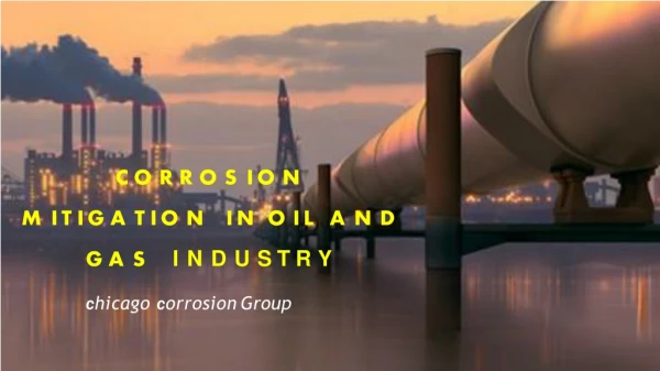
Corrosion in natural gas well tubing is a serious factor in failures of sour gas well under coexistence of H2S and CO2.<br>In order to satisfy the need of long term safe production, this paper proposes the methods of tubing sizes optimization<br>and material selection of tubing for preventing corrosion in high sour gas field under coexistence of H2S and CO2.<br>Nodal system analysis is used for optimization on tubing sizes for preventing corrosion, which is mainly for<br>preventing erosion. For material selection, traditional method is using sulfur-resistant steels. This paper proposes a<br>new option: using corrosion-resistant alloy. By analyzing of chemical corrosion test, traditional sulfur-resistant steels<br>may have severe corrosion in high sour gas wells under coexistence of H2S and CO2. For high sour gas wells under<br>the severe corrosion environment with high hydrogen sulfide and carbon dioxide content, selecting corrosionresistant<br>alloy is a good method. This paper optimizes the corrosion-resistant material selection by taking YB-3 gas<br>field as an example,. The experiment results show that there have serious galvanic corrosion and electrochemical<br>corrosion by corrosion coupon test and galvanic corrosion test for sulfur-resistant steel. The corrosion-resistant alloy<br>tubing may have a high initial investment; however, it has a very high safety and a low long-term operating cost, and<br>has no need for adding chemical corrosion inhibitor. For high sour gas fields under coexistence of H2S and CO2, this<br>measure can provide high cost performance and has a high resistance to corrosion. The study above has a good<br>applicability by testing, and can provide reference for corrosion preventing of the similar high sour gas fields under<br>coexistence of H2S and CO2

E N D
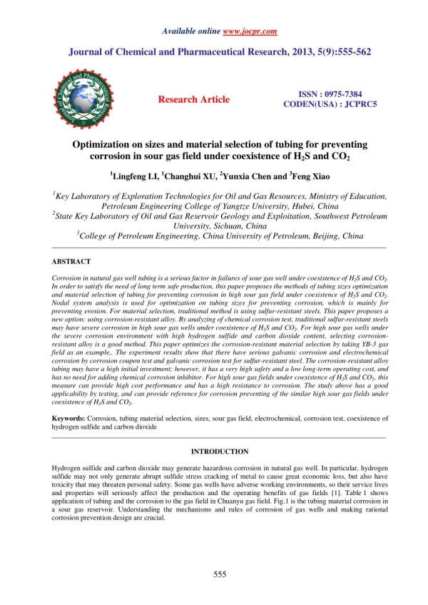
Available online www.jocpr.com Journal of Chemical and Pharmaceutical Research, 2013, 5(9):555-562 ISSN : 0975-7384 CODEN(USA) : JCPRC5 Research Article Optimization on sizes and material selection of tubing for preventing corrosion in sour gas field under coexistence of H2S and CO2 1Lingfeng LI, 1Changhui XU, 2Yunxia Chen and 3Feng Xiao 1Key Laboratory of Exploration Technologies for Oil and Gas Resources, Ministry of Education, Petroleum Engineering College of Yangtze University, Hubei, China 2State Key Laboratory of Oil and Gas Reservoir Geology and Exploitation, Southwest Petroleum University, Sichuan, China 3College of Petroleum Engineering, China University of Petroleum, Beijing, China _____________________________________________________________________________________________ ABSTRACT Corrosion in natural gas well tubing is a serious factor in failures of sour gas well under coexistence of H2S and CO2. In order to satisfy the need of long term safe production, this paper proposes the methods of tubing sizes optimization and material selection of tubing for preventing corrosion in high sour gas field under coexistence of H2S and CO2. Nodal system analysis is used for optimization on tubing sizes for preventing corrosion, which is mainly for preventing erosion. For material selection, traditional method is using sulfur-resistant steels. This paper proposes a new option: using corrosion-resistant alloy. By analyzing of chemical corrosion test, traditional sulfur-resistant steels may have severe corrosion in high sour gas wells under coexistence of H2S and CO2. For high sour gas wells under the severe corrosion environment with high hydrogen sulfide and carbon dioxide content, selecting corrosion- resistant alloy is a good method. This paper optimizes the corrosion-resistant material selection by taking YB-3 gas field as an example,. The experiment results show that there have serious galvanic corrosion and electrochemical corrosion by corrosion coupon test and galvanic corrosion test for sulfur-resistant steel. The corrosion-resistant alloy tubing may have a high initial investment; however, it has a very high safety and a low long-term operating cost, and has no need for adding chemical corrosion inhibitor. For high sour gas fields under coexistence of H2S and CO2, this measure can provide high cost performance and has a high resistance to corrosion. The study above has a good applicability by testing, and can provide reference for corrosion preventing of the similar high sour gas fields under coexistence of H2S and CO2. Keywords: Corrosion, tubing material selection, sizes, sour gas field, electrochemical, corrosion test, coexistence of hydrogen sulfide and carbon dioxide _____________________________________________________________________________________________ INTRODUCTION Hydrogen sulfide and carbon dioxide may generate hazardous corrosion in natural gas well. In particular, hydrogen sulfide may not only generate abrupt sulfide stress cracking of metal to cause great economic loss, but also have toxicity that may threaten personal safety. Some gas wells have adverse working environments, so their service lives and properties will seriously affect the production and the operating benefits of gas fields [1]. Table 1 shows application of tubing and the corrosion to the gas field in Chuanyu gas field. Fig.1 is the tubing material corrosion in a sour gas reservoir. Understanding the mechanisms and rules of corrosion of gas wells and making rational corrosion prevention design are crucial. 555
Lingfeng LI et al ______________________________________________________________________________ J. Chem. Pharm. Res., 2013, 5(9):555-562 Fig.1: The tubing corrosion in a sour gas reservoir This paper mainly study the methods and procedure oftubing sizes optimization, and material selection of tubing for preventing corrosion in high sour gas well under coexistence of H2S and CO2. Table 1: Application of tubing to the high sour gas well in Chuanyu gas field Tubing Steel Grade (g/m3) (g/m3) Cheng 34 KO80S Zhang 6 NT80SS 0.005 101.87 C75 C95 Chi 18 KO95SS 0.058 15.057 BGC90 NT80SS METHODS AND PROCEDURE OF TUBING SIZES OPTIMIZATION FOR PREVENTING CORROSION The tubing size optimization for gas wells is based on nodal system analysis. H2S CO2 Corrosion Description Well No. Concentration Concentration SM90S 3.566 50.724 Weight loss, pitting, fracture Weight loss, fracture, and dropout Cheng 18 3.59 51.199 Pitting, weight loss Weight loss, pitting, deformation and dropout Tieshan 12 15.16 16.501 Weight loss, pitting, fracture and dropout Fig.2: Producing system of natural gas well(1-Formation; 2-Well bottom; 3-Pump intake; 4- Pump discharge; 5-Wellhead; 6-Surface separator; 7-Fluid level; 8-Casinghead) Oil and gas may flow through several components from the reservoir to the surface separator, as shown in Fig.2. From the point of pressure loss, the total pressure loss along the way from the reservoir to the surface separator includes six components of loss. Methods: The tubing size sensitivity analysis for gas wells is based on nodal system analysis [2]. For gas wells, the size range of production casing can be determined on the basis of tubing size sensitivity analysis. The pressure loses 556
Lingfeng LI et al ______________________________________________________________________________ J. Chem. Pharm. Res., 2013, 5(9):555-562 flow through the porous medium, completion, tubing string, and flow line are regarded as subsystem A , B , C , and D respectively. The pressure system of the entire production consists of the four pressure subsystems above. Fig.3: Drawing dynamic curve using nodal analysis Drawing dynamic curve using nodal analysis 35 Wellhead pressure(MPa) 30 25 pressure into the node (MPa) Outflow pressure of node (MPa) 20 15 10 5 0 1 2 3 4 5 6 7 8 9 10 11 Yield Fig.4: Simulation of pressure of well dynamic curve using nodal analysis Fig.3 is drawing dynamic curve using nodal analysis. Fig.4 is simulation of pressure of well dynamic curve using nodal analysis. During the flowing production, the flow in tubing can be analyzed by the vertical multiphase flow in pipe. The most significant factors affecting the pressure gradient distribution for vertical multiphase flow are tubing size, flow rate, gas-liquid ratio, viscosity, and water-cut. For a designed well, gas-liquid ratio, viscosity, and water-cut are basically in a range while the flow rate can be controlled and changed. According to the multiphase flow theory, there is an optimum tubing size for which the pressure gradient or pressure loss in the well is minimum at each flow rate. When the flow rate is fixed, tubing size too small will result in high flow velocity that leads to high friction pressure loss; tubing size too large will cause low flow velocity that leads to serious slippage effect. Thus only when the proper tubing size is used can the sum of the friction pressure loss and the slippage loss be minimum, and the maximum energy utilization efficiency be achieved. Since production rate is an important factor of tubing size optimization, and there are different optimum tubing sizes for different flow rate, production rates should be considered the variable in all analyses. During the flow from reservoir to wellhead, production rate is closely related to pressure, hense, pressure is generally regarded as another variable. Usually, the effect of tubing size is analyzed according to pressure-rate (p-Q) coordinate plot, and nodal analysis is applied to determine optimum tubing size. Procedure: Optimization on tubing sizes for preventing corrosion in high sour gas well under coexistence of H2S and CO2 is mainly to prevent erosion. First of all, apply the nodal system analysis to the optimum tubing size determination by the oil production optimization, and select the basic production casing size. Then consider the requirements of tubing sizes for preventing erosion in high sour gas well, and determine the optimal tubing sizes for preventing corrosion in high sour gas wellis. A serious erosion may occur in the tubing of a gas well due to excessive flow velocity, thus leading to premature failure of the tubing. The Beggs formula is generally used for calculation. 557
Lingfeng LI et al ______________________________________________________________________________ J. Chem. Pharm. Res., 2013, 5(9):555-562 1) Beggs erosion velocity formula, as shown in Equation (1) [3]: C V (1) e g where: Ve=erosion flow velocity of erosion, m/s; C=empirical constant (Corrosion rate can be controlled if flow =gas density, kg/m3. 2) Anti-erosion production rate formula, as shown in Equation (2): 55.164 10 ( ) g g velocity is lower than the critical flow velocity.); p (2) 4 0.5 q AZT max limiting anti-erosion production rate, 104m3/d; A=internal cross-sectional area, m2; p= mean pressure q where: in tubing, MPa; T=mean temperature in tubing, K; Z=gas deviation factor under bottomhole condition, dimensionless; g relative density of gas. The minimum anti-erosion tubing sizes can be calculated using Equation (2) under different flowing bottomhole pressures and gas production rates as listed in Table 2. Table 2: Minimum Anti-Erosion Tubing Sizes Flowing Bottomhole Pressure (MPa) 200 30 97.46 40 91.52 50 87.83 60 85.33 OPTIMAL SELECTION ON MATERIAL OF TUBING FOR PREVENTING CORROSION IN SOUR GAS WELLUNDER COEXISTENCE OF H2S AND CO2 Proper selection of the material of tubing is a key problem in corrosion prevention of oil and gas wells. Improper selection of material may not only cause waste, but it may also generate unsafe conditions. The produced gas with high content of CO2, H2S, and elemental sulfur, and so on, in some gas wells make the corrosion in the gas production system and station and field equipment very serious. Fig.5 is the tubing corrosion in sour gas reservoirs under coexistence of H2S and CO2. In general, hydrogen sulfide–containing natural gas also contains a certain quantity of carbon dioxide [4]. max Daily Gas Production Rate (104m3/d) 300 400 119.4 137.9 112.2 129.6 107.7 124.4 104.6 120.9 500 154.2 145 139.2 135.2 600 168.9 158.8 152.5 148.2 Fig.5: The tubing corrosion in sour gas reservoirs under coexistence of H2S and CO2 For instance, both carbon dioxide and hydrogen sulfide corrosion should be considered for the ordovician gas reservoir in the Tazhong I zone, and corrosion-resistant material is required in the light of the partial pressures of hydrogen sulfide and carbon dioxide (Table 3). 558
Lingfeng LI et al ______________________________________________________________________________ J. Chem. Pharm. Res., 2013, 5(9):555-562 Table 3: Partial pressures of H2S and CO2 in in Tazhong I zone Partial Pressure of H2S (MPa) 0.071 0.007 0.128 0.019 Partial Pressure of CO2 (MPa) 1.987 2.160 1.274 1.546 Reservoir Pressure (MPa) H2S Content (%) CO2 Content (%) Well No. TZ622 TZ82 TZ622 TZ621 47.2 63.164 55.636 57.253 0.15 0.011 0.230 0.034 4.21 3.42 2.29 2.7 For a serious corrosive environment (such as high pressure and carbon dioxide; high pressure, carbon dioxide, and hydrogen sulfide), stainless steel, or alloy steel should be adopted in a corrosion-resisting design. Stainless steel or alloy steel is expensive and has a long delivery time. They also have down hole service environment restrictions. Thus test evaluation and technical economical analysis are required. This paper mainly discusses the severe corrosion environment with high hydrogen sulfide and carbon dioxide content Sulfide stress cracking resisting carbon steel and low-alloy steel may generate serious weight-loss corrosion and pitting corrosion under the condition of unfavorable corrosive media type combination of oil or gas wells and the interaction of content, pressure, and temperature. Thus corrosion-resistant alloy steel should be predominantly adopted. In general, nickel- based alloy material can be selected under this severe corrosion environment condition. In recent years, economical H2S/CO2 corrosion-resistant low-alloy steels have been developed. In addition, protective coating and corrosion inhibitor are also required. The H2S/CO2 corrosion control techniques should be evaluated and optimized. When the development of oil and gas reservoirs is started, whether down hole strings and surface equipment adopt expensive corrosion-resistant material or coating protection should be determined. The future corrosion severity should be predicted and economical corrosion resisting measures should be determined when an oil and gas reservoir development program is formulated on the basis of the data of one or two wells drilled first. Table 4 shows Sumitomo metal corrosion resistance classification standard[5]. Table 4: Sumitomo metal corrosion resistance classification standard Corrosion Rate, mm/a <0.1 Corrosion resistance is strictly required. 0.1~1.0 Corrosion resistance is not strictly required. >1.0 Low corrosion resistance and low practical value. Technical margins of corrosion-resistant material selection. Selecting corrosion-resistant material should be considered first as a corrosion prevention measure. The application of corrosion-resistant material is mainly related to the following: a. Oil and gas well production environments b. Material performance, laboratory test, evaluation data, and on-site use experience c. Whether corrosion inhibitor, cathodic protection, and comprehensive protective measures are adopted d. Economic evaluation To sum up, the selection of material should meet the requirements of rupture protection, strength, weldability, and so on, and should also be economically reasonable. Corrosion-resistant material selection procedure is as follows: 1. Listing the requirements for material 2. Finding, evaluating possible material by experience and selecting economic material. APPLICATION In this paper, we take YB-3 gas field as an example, which is a typical sulfide containing gas field, which is located in the Sichuan Basin, southwest China. Main gas sample analysis of YB-3 gas field is in Table 5. Table 5: gas analysis of gas samples for YB-3 gas field Well Code Methane Ethane Propane Nitrogen Helium H2S CO2 No.1 80.3 0.05 0. No.3 84.6 0.08 0.03 No.6 84.8 0.09 0 No.7 81.3 0.07 0 Usable Range Content of Natural Gas Constituent (%) 0.65 0.71 0.45 1.34 0.002 9.82 9.13 0.017 8.77 5.44 0.018 8.28 6.21 0.016 10.4 6.74 559
Lingfeng LI et al ______________________________________________________________________________ J. Chem. Pharm. Res., 2013, 5(9):555-562 Contents of H2S and CO2 in YB-3 gas field are very high, so taking effective anti-corrosion measures is very necessary. Anti-erosion performance analysis of gas tubing. According to API RP 14E standard, the use of basic data to calculate the limiting anti-erosion production rate for different tubing sizes is in Table 6. Table 6: limiting anti-erosion production rate for different tubing sizes in YB-3 gas field Flowing Wellhead Pressure (MPa) 15 36.72 20 41.05 25 47.40 30 53.0 10 0.7443 15 38.48 20 44.46 10 32.01 15 39.2 20 45.27 25 50.61 Optimization on Material selection of Tubing for Preventing Corrosion. For high-temperature, high-pressure, high productivity, and high sour gas wells under coexistence of H2S and CO2, similar to those of YB-3 gas field, selecting high-alloy austenitic corrosion-resistant alloy stainless steel or nickel-based corrosion-resistant alloy steel is the main measure of serious hydrogen sulfide and carbon dioxide corrosion prevention to ensure long-term, safe, and stable production and avoid well servicing and work over as far as possible to ensure stable natural gas supply. This type of corrosion resistant alloy has a chrome content of 20% to 30% and nickel content of 20% to 35%. High strength is achieved by cold working. It has the highest resistance to corrosion and the highest mechanical performance in all stainless steels. In corrosion-resistant alloys, Cr, Ni, and Mo are the most important basic alloying elements. The main compositions of corrosion-resistant alloys for tubing and casing are listed in Table 7 [6]. Different percentage contents and different manufacturing methods form different types of corrosion-resistant alloys. The aforementioned elements are crucial to the formation of stable protective corrosion product film on structural members [8]. Corrosion will start from the failure of protective corrosion product film. Table 7: The main compositions of corrosion-resistant alloys for tubing and casing Material Name C Si Mn G3 ≤0.015 ≤1.0 ≤1.0 825 ≤0.05 ≤0.5 ≤1.0 2205 ≤0.03 ≤1.0 ≤2.0 304 ≤0.07 ≤1.0 ≤2.0 P110SS 0.25 0.2 1.4 Hydrogen sulfide and carbon dioxide–resistant steels can be selected by using the steel grade selection diagrams of Sumitomo and NKK in accordance with the partial pressures of hydrogen sulfide and carbon dioxide and down hole temperature [7]. RESULTS AND DISCUSSION Considering the requirements of tubing sizes for preventing erosion in high sour gas well, the optimal tubing sizes for preventing corrosion in YB-3 gas field can be determined as list in Table 8. Table 8: Selection of tubing sizes for YB-3 gas field Single well production allocation (×104m3/d) Diameter of tubing(mm) 97.2 limiting anti-erosion production rate for different tubing sizes (104m3/d) Relative density of gas Well No. 62mm 76mm 88.3mm 97.2mm 55.02 61.524 71.04 79.42 49.94 61.16 70.62 50.88 62.32 71.96 80.45 74.98 83.83 96.79 108.22 68.05 83.34 96.231 69.33 84.91 98.05 109.62 96.09 107.43 124.04 138.69 87.21 106.81 123.33 88.85 108.82 125.65 140.48 1 0.7199 31.42 3 7 0.717 S Cr Ni Fe 21-3.5 19.5-23.5 21-23 17.0-19 0.15 balance 38-46 4.5-6.5 8.0-11 0.012 18-21 ≥22 balance balance balance ≤0.03 ≤0.03 ≤0.02 ≤0.03 ≤0.003 100~ 140 80~ 100 88.3 <50 50~80 76 62 560
Lingfeng LI et al ______________________________________________________________________________ J. Chem. Pharm. Res., 2013, 5(9):555-562 We can see from table 8 that calculating according to the wellhead pressure 25MPa, tubing diameter is 62 mm to avoid gas erosion phenomenon when yield is 50×104 m3/d or less. When yield is 50×104~80×104 m3/d, tubing diameter is 76 mm. When yield is 80×104~100×104 m3/d, tubing diameter is 88.3mm. When yield is 100×104~140×104 m3/d, tubing diameter is 97.2 mm. Based on such experiences in development of high sulfur content oil & gas field in foreign countries, such as Lacq Gas Field of France, Thamama Gas Field in the Middle East and Bearbery Gas Field in Canada, this article will mainly discuss two options: corrosion-proof plan of corrosion-resistant alloy tubing and corrosion-proof plan of sulfur-resistant tubing. (A) corrosion-proof plan of corrosion-resistant alloy tubing: Tubing of full well section is with high nickel alloy steel tubing (eg G3), and it has no need for adding corrosion inhibitor. But its cost is high, which is 10 to 15 times the cost of corrosion-resistant steel. (B) corrosion-proof plan of sulfur-resistant tubing: high nickel alloy steel is used for tubing for following the packer and above the safety valve. The scheme has two main problems: the first is sulfur-resistant steels under the high H2S, CO2 environment has severe corrosion; the second is the junction of a high sulfur-resistant steel and high nickel alloy has serious galvanic corrosion (Cao C.N., 2008). Experimental data of galvanic corrosion for high sulfur- resistant steels and high nickel alloy steel are shown in Table 9, Table 10 and Table 11. Table 9: Static corrosion coupon test data Index Temperature 40℃ 1.20 80℃ 5.99 120℃ 2.17 Table 10: Static galvanic corrosion test data Index temperature C-276 825 25℃ 0.95 0.94 80℃ 0.50 0.50 120℃ 0.09 0.02 Test medium: +3% sodium chloride, saturated hydrogen sulfide and carbon dioxide Table 11: Static galvanic corrosion test data Index Temperature C-276 120℃ 8.0 Description: Test medium: (0.5% acetic acid +3% sodium chloride) Galvanic corrosion and electrochemical corrosion experimental data above show that: 1. corrosion rate of anti-sulfur steel(40 ℃) is 0.67 ~ 1.20 mm / a, which is 8.8~15.7 times to ministerial standards; corrosion rate of anti-sulfur steel(80 ℃) is 0.503 ~ 5.99 mm / a, which is6.6 ~ 78.8 times to ministerial standards (Zhang B.H.,Cong W.B.,Yang P., 2011). So the corrosion is very serious. 2. galvanic corrosion(25 ~ 80 ℃) of sulfur resistant steel and four kinds of alloy is very serious, the corrosion rate is 0.30 ~ 0.95 mm / a, which is 3.9~ 2.5 times to ministerial standards. 3. galvanic corrosion(120℃) of sulfur resistant steel and alloy(C276, SM2535) is very serious, the corrosion rate is 8.0~11.0 mm / a, which is 105.3~144.7 times to ministerial standards. From the experimental data above, it is clear that there have serious galvanic corrosion and electrochemical corrosion for high sulfur-resistant tubing. Despite the high cost, the corrosion-resistant alloy has long service life. The service life of corrosion-resistant alloy tubing is similar to the production lives of several gas wells. The corrosion- resistant alloy tubing can be repeatedly used in multiple wells and has no need for adding corrosion inhibitor and replacing tubing, and so on. Thus the total cost is reasonable for corrosion-resistant alloy tubing. For high-pressure and high-productivity oil and gas wells that have strong corrosiveness, this may be an effective and economic corrosion prevention measure. average corrosion rate(mm/a) 3%NaCl+ 3%NaCl+0.5%CH3COOH + saturated H2S and CO2 saturated H2S and CO2 0.67 0.503 0.22 galvanic corrosion rate(mm/a) G3 0.65 0.45 0.6 SM-2535 0.30 0.56 0.03 galvanic corrosion rate(mm/a) 825 13 G3 9.0 SM-2535 11.0 561
Lingfeng LI et al ______________________________________________________________________________ J. Chem. Pharm. Res., 2013, 5(9):555-562 CONCLUSION In order to satisfy the need of long term, safe and reasonable production of sour natural gas well under coexistence of H2S and CO2, this paper introduces the methods and procedure oftubing sizes optimization, material selection of tubing for preventing corrosion in high sour gas well. Aiming at the actual situation of YB-3 gas field, which is a typical sulfide containing gas field under coexistence of H2S and CO2, this paper optimizes the tubing sizes and material selection of tubing for preventing corrosion. Optimization on tubing sizes for preventing corrosion in high sour gas well is mainly to prevent erosion. Material selection of tubing for preventing corrosion mainly includes two options: traditional corrosion-proof plan of sulfur-resistant tubing and corrosion-proof plan of corrosion-resistant alloy tubing. Sulfur-resistant steels in high sour gas wells under coexistence of H2S and CO2 may have severe corrosion. Despite the high cost, the corrosion-resistant alloy has long service life. The service life of corrosion- resistant alloy tubing is similar to the production lives of several gas wells. The corrosion-resistant alloy tubing can be repeatedly used in multiple wells and has no need for adding corrosion inhibitor and replacing tubing, and so on. Thus the total cost is reasonable. For high-productivity gas wells under coexistence of H2S and CO2, this can provide high cost performance and has a high resistance to corrosion. The study above has a good applicability by testing, and can provide reference for corrosion preventing of the similar high sour gas fields under coexistence of H2S and CO2. Acknowledgments This work was supported by Petro China Innovation Foundation (NO. 2011D-5006-0605), Department of Education in Hubei Province(NO. Q20091212) and National Natural Science Foundation of China(NO. 51378077). REFERENCES [1]Lu Q.M. et al., 2001. The Corrosion and Protection in Petroleum Industry, Beijing: Chemical Industry Press, ISBN: 750253417. [2]LI Y.C., 2009. Oil Production Engineering. 2nd Edn., Beijing: Petroleum Industry Press, I S B N: 9787502165888. [3]LI S.L., 2008. Natural Gas Engineering. Beijing: Petroleum Industry Press, ISBN: 9787502165895. [4]Zhang Y.Y. et al., 2000. Carbon Dioxide Corrosion and Control, Beijing: Chemical Industry Press, ISBN: 9787502528430. [5]Sun Q.X. et al., 2001. Material Corrosion and Protection. Beijing: Metallurgical Industry Press, ISBN: 7502426590. [6]Wan R.P., 2011. Advanced Well Completion Engineering. U.S.: Gulf Professional Publishing, ISBN: 9780123858689. [7]Cao C.N., (Trans.), 2008. Principles of Electrochemistry of Corrosion, 3re Edn., Beijing: Chemical Industry Press, ISBN: 9787122020451 [8]Zhang B.H.,Cong W.B.,Yang P., 2011. Metal Electrochemical Corrosion and Protection, Beijing: Chemical Industry Press, ISBN: 978750257. 562