Download
1 / 6
60 likes | 94 Vues
Crankshaft is the main component part of an engine. The main aim of this thesis is to select the crankshaft materials with minimum Von Misses stress and displacement. That is considered material selection, theory and calculation of crankshaft for static load. The function of the crankshaft is to convert the reciprocation motion of the piston to rotary motion of the flywheel. If the crankshaft is suddenly deformable, the engine will not work. The type of the crankshaft is used for four cylinder, four stroke 2C Diesel Engine Light Truck , which is fully supported, multi throws, centre crankshaft. The compression ratio of this engine is 22.5. This thesis is mainly compared the Von Misses stresses and displacement of three different materials. As the crankshaft is subjected to complex bending, shear and twisting loads, it needs to be well designed quality material to withstand the high stresses. The total length of the crankshaft is 460 mm. The crankpin diameter is 50 mm and the main diameter is 56 mm. The crankpin length is 28 mm and the main journal length is 29 mm. In this thesis, crankshaft design is modelled and compared the simulation results with acting static load on the crankshaft by using AutoDesk Inventor software. In AutoDesk Inventor software, it is needed to apply boundary condition on the existing crankshaft for stress analysis report. The gas force acting on the middle of the crankpins is 44198.512 N. The combustion pressure was used to calculate the gas force acting on the crankshaft and modelled the geometry of crankshaft. Finally, Carbon steel will be selected because it has minimum Von Misses stress and displacement. Ei Cho Cho Theik | Khaing Zar Nyunt | Hnin Yu Yu Kyaw "Material Selection of Crankshaft for 2C Diesel Engine" Published in International Journal of Trend in Scientific Research and Development (ijtsrd), ISSN: 2456-6470, Volume-3 | Issue-4 , June 2019, URL: https://www.ijtsrd.com/papers/ijtsrd25171.pdf Paper URL: https://www.ijtsrd.com/engineering/mechanical-engineering/25171/material-selection-of-crankshaft-for-2c-diesel-engine/ei-cho-cho-theik<br>

E N D
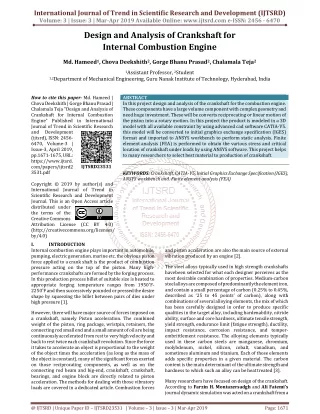
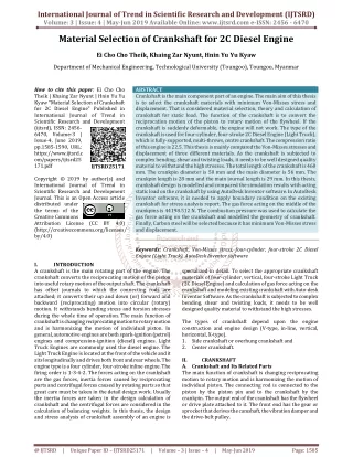
International Journal of Trend in Scientific Research and Development (IJTSRD) Volume: 3 | Issue: 4 | May-Jun 2019 Available Online: www.ijtsrd.com e-ISSN: 2456 - 6470 Material Selection of Crankshaft for 2C Diesel Engine Ei Cho Cho Theik, Khaing Zar Nyunt, Hnin Yu Yu Kyaw Department of Mechanical Engineering, Technological University (Toungoo), Toungoo, Myanmar How to cite this paper: Ei Cho Cho Theik | Khaing Zar Nyunt | Hnin Yu Yu Kyaw "Material Selection of Crankshaft for 2C Diesel Engine" Published in International Journal of Trend in Scientific Research and Development (ijtsrd), ISSN: 2456- 6470, Volume-3 | Issue-4, June 2019, pp.1585-1590, URL: https://www.ijtsrd.c om/papers/ijtsrd25 171.pdf Copyright © 2019 by author(s) and International Journal of Trend in Scientific Research and Development Journal. This is an Open Access article distributed under the terms of the Creative Commons Attribution License (CC BY 4.0) (http://creativecommons.org/licenses/ by/4.0) I. INTRODUCTION A crankshaft is the main rotating part of the engine. The crankshaft converts the reciprocating motion of the piston into useful rotary motion of the output shaft. The crankshaft has offset journals to which the connecting rods are attached; it converts their up and down (or) forward and backward (reciprocating) motion into circular (rotary) motion. It withstands bending stress and torsion stresses during the whole time of operation. The main function of crankshaft is changing reciprocating motion to rotary motion and is harmonizing the motion of individual piston. In general, automotive engines are both spark-ignition (petrol) engines and compression-ignition (diesel) engines. Light Truck Engines are commonly used the diesel engine. The Light Truck Engine is located at the front of the vehicle and it sits longitudinally and drives both front and rear wheels. The engine type is a four cylinder, four-stroke inline engine. The firing order is 1-3-4-2. The forces acting on the crankshaft are the gas forces, inertia forces caused by reciprocating parts and centrifugal forces caused by rotating parts so that great care must be taken in the detail design work. Usually the inertia forces are taken in the design calculation of crankshaft and the centrifugal forces are considered in the calculation of balancing weights. In this thesis, the design and stress analysis of crankshaft assembly of an engine is ABSTRACT Crankshaft is the main component part of an engine. The main aim of this thesis is to select the crankshaft materials with minimum Von-Misses stress and displacement. That is considered material selection, theory and calculation of crankshaft for static load. The function of the crankshaft is to convert the reciprocation motion of the piston to rotary motion of the flywheel. If the crankshaft is suddenly deformable, the engine will not work. The type of the crankshaft is used for four-cylinder, four-stroke 2C Diesel Engine (Light Truck), which is fully-supported, multi-throws, centre crankshaft. The compression ratio of this engine is 22.5. This thesis is mainly compared the Von-Misses stresses and displacement of three different materials. As the crankshaft is subjected to complex bending, shear and twisting loads, it needs to be well designed quality material to withstand the high stresses. The total length of the crankshaft is 460 mm. The crankpin diameter is 50 mm and the main diameter is 56 mm. The crankpin length is 28 mm and the main journal length is 29 mm. In this thesis, crankshaft design is modelled and compared the simulation results with acting static load on the crankshaft by using AutoDesk Inventor software. In AutoDesk Inventor software, it is needed to apply boundary condition on the existing crankshaft for stress analysis report. The gas force acting on the middle of the crankpins is 44198.512 N. The combustion pressure was used to calculate the gas force acting on the crankshaft and modelled the geometry of crankshaft. Finally, Carbon steel will be selected because it has minimum Von-Misses stress and displacement. Keywords: Crankshaft, Von-Misses stress, four-cylinder, four-stroke 2C Diesel Engine (Light Truck), AutoDesk Inventor software specialized in detail. To select the appropriate crankshaft materials of four-cylinder, vertical, four-stroke Light Truck (2C Diesel Engine) and calculation of gas force acting on the crankshaft and modeling existing crankshaft with Auto-desk Inventor Software. As the crankshaft is subjected to complex bending, shear and twisting loads, it needs to be well designed quality material to withstand the high stresses. The types of crankshaft depend upon the engine construction and engine design (V-type, in-line, vertical, horizontal, X-type). 1.Side crankshaft or overhung crankshaft and 2.Center crankshaft. II. CRANKSHAFT A.Crankshaft and Its Related Parts The main function of crankshaft is changing reciprocating motion to rotary motion and is harmonizing the motion of individual piston. The connecting rod is connected to the piston by the piston pin and to the crankshaft by the crankpin. The output end of the crankshaft has the flywheel or drive plate attached to it. The front end has the gear or sprocket that derives the camshaft, the vibration damper and the drive-belt pulley. IJTSRD25171 @ IJTSRD | Unique Paper ID – IJTSRD25171 | Volume – 3 | Issue – 4 | May-Jun 2019 Page: 1585
International Journal of Trend in Scientific Research and Development (IJTSRD) @ www.ijtsrd.com eISSN: 2456-6470 Fg = (Gas pressure – Atmospheric pressure) × Area πd2 Fg = (Pg – Pa) × 4 Where, d = Piston diameter (85.979 mm) Pa = Atmospheric pressure (0.1 MPa) Design of Main Journal The bending moment at the juncture of the crank arm, 2 2 Allowable bending stress for main journal, 32M σ = L L = + + M H t 2 c m 2 Equation 3.29 m b 3 m πD Where, Dm = Diameter of the shaft at the junction of the crank arm. M 32 D × Design of Crankshaft Maximum Principal Stress ( σ ) ( y x y x 2 2 x σ= Stress in x direction, MPa or N/mm2 y σ = Stress in y direction, MPa or N/mm2 τ = Shear stress, MPa Minimum Principal Stress ( 2 σ ) ( y x y x 2 2 Maximum Shear Stress ( max τ ( xy τ 2 Torsional Stress (T) The torsional formula is, T = I r T = Torque or torsional moment, N-mm J = Polar moment of inertia, mm2 J = d 32 J = ( d d 32 4 id = Outer diameter of hollow shaft G = Modulus of elasticity in shear or modulus of rigidity, MPa θ = Angle of twist, radians 1.Piston 2.Piston rings 3.Piston pin 4.Connecting rod 5.Connecting rod bolt 6.Connecting rod bearing shell 7.Connecting rod cap Figure 1: Crankshaft and Its Related Parts 8.Main bearings 9.Main bearing cap bolt 10. Main bearing cap 11. Crankshaft 12. Flywheel 13. Flywheel bolt 14. Ring gear × = m 3 m σ π b 1 ) B.Design Properties for Engine Crankshaft Crankshaft should have the following design properties. 1.It must be convenient, easy and safe to operate. 2.It should be durable, reliable, simple and maintained. 3.It should be produced with low carbon steel. Crankshaft should be designed and constructed using carefully selected materials. The materials to be selected should have the following properties: 1.High strength, ductility 2.Wear resistance 3.Good cast ability 4.Excellent mach inability 5.Resistance to impact load 6.Low cost III. DESIGN THEORY A. Design Theory of Forces Acting On the Crankshaft The forces acting on the principal moving parts of a reciprocating engine are the gas pressure force, the inertia forces of the reciprocating parts, and the inertia and centrifugal forces of the rotating parts. The gas pressure forces are the principal forces. The inertia forces may be considerably larger at high speeds. The centrifugal forces also increase rapidly with an increase in speed.The gas pressure and inertia forces result in a net force on the piston that reduced by the shearing force of the oil film between the piston assembly and the cylinder wall. The net result is a force along the connecting rod that resolves itself into a turning effort or torque on the crankshaft. Gas Forces Before calculate the gas forces, it need to calculate the gas pressure of the whole operating cycle. + − 2 σ σ σ σ σ = + + 2 τ 1 xy xy ) 2 + − σ σ σ σ σ = 2 − + τ 2 xy ) ) 2 − σ σ τ 2 x y ± + = max Gθ τ = J π 4 , d = Solid shaft diameter ), 4 π d = Outer diameter of hollow shaft 4 4 0− 0 i @ IJTSRD | Unique Paper ID – IJTSRD25171 | Volume – 3 | Issue – 4 | May-Jun 2019 Page: 1586
International Journal of Trend in Scientific Research and Development (IJTSRD) @ www.ijtsrd.com eISSN: 2456-6470 L = Length of shaft, mm r = Distance from the Neutral axis to the top most fiber, mm d (for solid shaft) C.Boundary Conditions 1.Select Materials 2.Fixed constraint 3.General Force 4.Meshing Setting 5.Convergence Setting 6.Create simulation D. Meshing Setting = 2 d0 (for hollow shaft) = 2 Bending Stresses ( σ) b σ M = E= b I R C M = Bending moment, N-mm I = Second moment of area, mm4 I = d 64 I = ( d d 64 E = Modulus of elasticity, MPa R = Radius of curvature, mm c = Distance from the axis to the extreme fiber, mm d (for solid shaft) π , (for solid shaft) 4 ), π (for hollow shaft) 4 4 0− i Figure 3: Meshed Modeled of Crankshaft E. Convergence Setting = 2 d0 (for hollow shaft) = 2 B.Input Data Table.1. The Gas Forces of the Whole Process Process Gas Pressure, MPa Gas Force, N Admission Compression Combustion Expansion Exhaust 0.11 IV. RESULT DATA A.Static Analysis of Crankshaft Static analysis is an engineering discipline that determines the stress in materials and structures subjected to static or dynamic forces or loads. The aim of the analysis is usually to determine whether the element or collection of elements, usually referred to as a structure or component, can safely withstand the specified forces and loads. This is achieved when the determined stress from the applied force(s) is less than the yield strength the material is known to be able to withstand. This stress relationship is commonly referred to as factor of safety (FOS) and is used in many analyses as an indicator of success or failure in analysis B. Modeling of Crank shaft 0.09622 5.509 7.7126 0.3706 – 21.947 31404.481 44198.512 1571.096 58.059 Figure 4: Convergence Setting F. Create Simulation Figure 5: Applying Boundary Condition G. Materials Used for Crankshaft 1.Cast Iron 2.Alloy Steel 3.Carbon Steel Figure 2: Crankshaft modeled using Auto-desk Invertor software @ IJTSRD | Unique Paper ID – IJTSRD25171 | Volume – 3 | Issue – 4 | May-Jun 2019 Page: 1587
International Journal of Trend in Scientific Research and Development (IJTSRD) @ www.ijtsrd.com eISSN: 2456-6470 Table2. Properties of Materials Mass Density (g/cm3) (MPa) 7.15 758 Yield Strength Young Modulus (GPa) 120.5 Poisson’s Ratio Materials Cast Iron Alloy Steel Carbon Steel 0.3 7.73 250 0.3 205 7.85 350 0.29 200 H. Stress Analysis Report Figure 10: Von-misses Stress of Alloy Steel Figure 6: Von-misses Stress of Cast Iron Figure 11: 3rd Principal stress of Alloy Steel Figure 7: 3rd Principal stress of Cast Iron Figure 12: Displacement of Alloy Steel Figure 8: Displacement of Cast Iron Figure 13: Safety Factor of Alloy Steel Figure 14: Von-misses Stress of Carbon Steel Figure 9: Safety Factor of Cast Iron @ IJTSRD | Unique Paper ID – IJTSRD25171 | Volume – 3 | Issue – 4 | May-Jun 2019 Page: 1588
International Journal of Trend in Scientific Research and Development (IJTSRD) @ www.ijtsrd.com eISSN: 2456-6470 Figure 18: Comparisons of Von-misses Stress of Materials Figure 15: 3rd Principal Stress of Carbon Steel Figure 16: Displacement of Carbon Steel Figure 19: Comparisons of Displacement of Materials V. In this paper, the author studied the type of crankshaft, theory and calculations of crankshaft. It is considered about the crankshaft material selection by using Autodesk Inventor software. Firstly, the existing data of the crankshaft is collected in Mechanical Engineering ICE Workshop. The crankshaft design shall account for calculating at pressure, temperature and engine parameter. By using Autodesk Inventor software, materials are selected with three different materials; cast iron, alloy steel and carbon steel. And then, fixed constraint can be defined on the faces of the crankshaft ends and force on the crankpins and meshing setting is adjusted. The excess air coefficient is the ratio of the amount of air participating in fuel combustion to that theoretically required. The amount of air that takes place in the combustion of 1 kg of liquid fuel is equal to the theoretical amount of air participating in the combustion of 1 kg of liquid fuel, α will be equal to 1. If α is less than 1, the mixture is called rich mixture and if α is greater than 1, the mixture is called lean mixture. The most stable combustion is obtained at α=1.1 to 1.3. In this design, α=1.1 is used to get the maximum power. From this power, the stresses in engine parts are calculated. In thermal calculation, the coefficient of heat utilization, ξ is taken from the type of engine speed, cooling conditions and the design of combustion chambers. In this design, we take ξ=0.7 which shows there is a little heat transfer to wall and only a little after burning during expansion. In the calculation of engine parameters, the polytrophic exponent of compression n1 is between the ranges of 1.3 to 1.4 and taken as 1.3 to get the approximate value with the existing crankshaft. If the calculation uses higher values, the corresponding pressure will be greater and finally the dimensional calculations will give very larger values. The crankshaft dimensions are the same size as the CONCLUSION Figure 17: Safety Factor of Carbon Steel Table.3. Results Table of Materials Displacement (mm) Safety factor(ul) 3rd principal stress(MPa) stress(MPa) stress(MPa) 1st principal Von-misses Materials Cast iron 772 887.9 173 1.331 0.98 Alloy steel 838.1 878.6 194.3 0.7868 0.3 Carbon steel 555.3 629.1 181.7 0.7993 0.63 @ IJTSRD | Unique Paper ID – IJTSRD25171 | Volume – 3 | Issue – 4 | May-Jun 2019 Page: 1589
International Journal of Trend in Scientific Research and Development (IJTSRD) @ www.ijtsrd.com eISSN: 2456-6470 [3]Farzin H.Montazersadgh and Ali Fatemi, Stress Analysis and Optimization of Crankshafts Subject to Dynamic Loading, University of Toledo, American Iron and Steel Institute, 2007. existing crankshafts. The main aim of this thesis is to select the crankshaft materials with minimum von-misses stress and displacement for 2C Diesel Engine (Light Truck). Acknowledgement Firstly, the author would like to thank my parents for their best wish to join the master course at TU (Toungoo). The author greatly expresses her thanks to all persons whom will concern to support in preparing this paper. The team wishes to extend our gratitude to all teachers that have taught there from childhood up to now. Finally, the team would like to express warmly the gratitude to all persons who were directly or indirectly involved towards the successful completion for this paper. References [1]Selection of Crankshaft Material by Numerical Method, B.E. Thesis, TU TOUNGOO, 2018. [4]Myo ZawMin, Mg, Design and Fabrication of 2.4 Liter Diesel Engine Crankshaft, Ph.D, Thesis, Y.T.U, 2003. [5]Aung Nay Lin, Mg, Design Calculations of Crankshaft and Flywheel (TOYOTA 2.0 Liter 2L Diesel Engine), M .E Thesis, PAKOKKU, 2007. [6]William H. Crouse: Automotive Engines (Construction, Operation and Maintenance), McGraw-Hill Book Company Inc, 1955. [7]Jeremy Hirschhorn, Dynamic of Machinery, Thomas Nelson and Sons Ltd, 1967. [8]Maleev, V.L: Diesel Engine Operation and Maintenance, McGraw-Hill Book companyInc, 1954. [2]Myat Su Mon Win, Ma, Design and Fabrication of Crankshaft for Light Truck (2C Diesel Engine), M .E Thesis, TOUNGOO, 2012. [9]Lester C. Lichty, Internal Combustion Engines, Sixth Edition, McGraw-Hill Book company, Inc. New York, 1951 @ IJTSRD | Unique Paper ID – IJTSRD25171 | Volume – 3 | Issue – 4 | May-Jun 2019 Page: 1590