Download
1 / 8
80 likes | 118 Vues
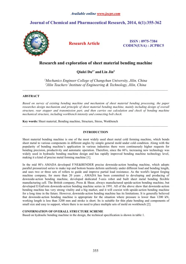
Based on survey of existing bending machine and mechanism of sheet material bending processing, the paper<br>researches design mechanism and principle of sheet material bending machine, mainly including design of overall<br>structure, rear stopper and transmission part, and then carries out calculation and check of bending machine<br>mechanical structure, including workbench intensity and connecting bolt check

E N D
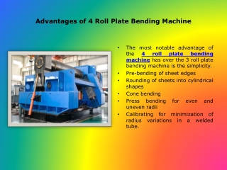
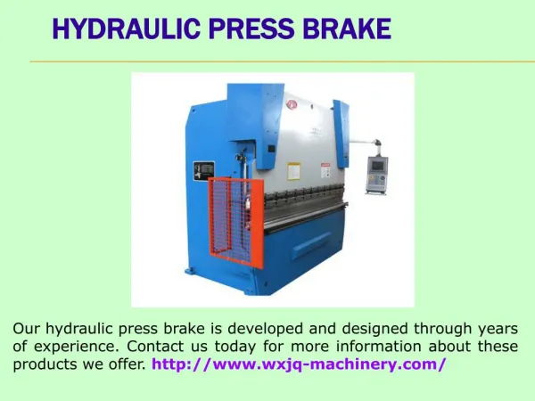
Available online www.jocpr.com Journal of Chemical and Pharmaceutical Research, 2014, 6(1):355-362 ISSN : 0975-7384 CODEN(USA) : JCPRC5 ResearchArticle Research and exploration of sheet material bending machine Qiulei Du1*andLin Jin2 1Mechanics Engineer College of Changchun University, Jilin, China 2Jilin Teachers’Institute of Engineering & Technology, Jilin, China _____________________________________________________________________________________________ ABSTRACT Based on survey of existing bending machine and mechanism of sheet material bending processing, the paper researches design mechanism and principle of sheet material bending machine, mainly including design of overall structure, rear stopper and transmission part, and then carries out calculation and check of bending machine mechanical structure, including workbench intensity and connecting bolt check. Key words: Sheet material, Bending machine, Structure, Stress, Workbench _____________________________________________________________________________________________ INTRODUCTION Sheet material bending machine is one of the most widely used sheet metal cold forming machine, which bends sheet metal to various components in different angles by simple general mold under cold condition. Along with the popularity of bending machine’s application in various industries there were continuously higher requests for bending precision, productivity and automatic operation. Therefore, since the 60’s, increasing new technology was widely used in hydraulic bending machine design and has rapidly improved bending machine technology level, making it a kind of precise metal forming machine [1]. In the mid 80’s AMADA developed F/NE&BENDER precise downside-action bending machine, which adopts parallel pressurized series to make top and bottom beams deform uniformly under different load and bending length, and uses two or three sets of rollers to guide and improve partial load resistance. As the world's largest forging machine company, for more than 20 years , AMADA has been committed to developing and producing of downside-action bending machine, developed dedicated 5-axis robot and built sheet metal bending flexible manufacturing cell. The British company, Press & Shear, always manufactured upside-action bending machine, but developed E/GaForm downside-action bending machine series in 1991. All of the above show that downside-action bending machine has very strong vitality and a big market, and it will coexist with upside-action bending machine for a long time in the future. However, downside-action bending machine has its limitations. It is generally believed that downside-action bending machine is appropriate for the situation where pressure is lower than 1200 kN, working length is less than 3200 mm and stroke is short. Its is suitable for thin plate bending and components of small size and easy to support, where there is no need to place multiple sets of mold on workbench [2]. CONFIRMATION OF OVERALL STRUCTURE SCHEME Based on hydraulic bending machine in the design, the technical specification is shown in table 1. 355
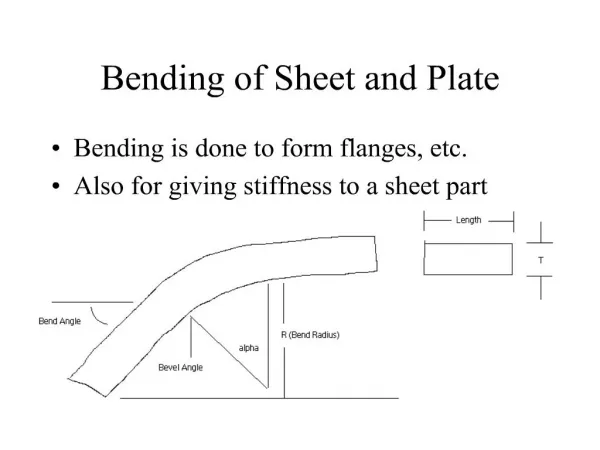
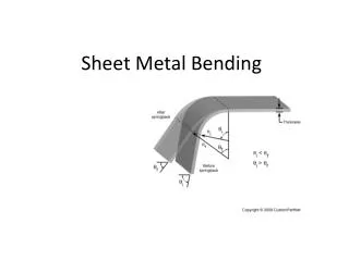
Qiulei DuandLin Jin ______________________________________________________________________________ J. Chem. Pharm. Res., 2014, 6(1):355-362 Table.1 Technical specification of bending machine No. 1 2 3 4 5 6 7 8 9 10 11 Parameter Value 500kN 2500mm 400mm 100mm 2000mm nominal pressure workbench length throat depth slide stroke column distance machine size descending speed of oil cylinder pressure speed of oil cylinder return stroke speed of oil cylinder main motor power weight 2600mm×1060mm×2030mm 80mm/s 20mm/s 65mm/s 5.5kw 3550kg According to the above design technical parameters, structure design is confirmed as follows. (1) Overall design: This design uses whole cast steel structure, where the main components are separately cast and then welded. The advantages of the structure are high intensity, good rigidity and large motion space for rear stopper, where fuel tank and some other important components can be placed on the machine body. But there is a disadvantage that joining precision demands for each component are very high due to the joining structure. (2) Rear stopper design: The position of rear stopper is presented in figure 1. There are two kinds of rear stoppers, namely hand-actuated and motor-driven adjusting types. The former is of simple structure and low cost, but it needs operator’s high quality and a great deal of experience. What’s more, when bending length changes, artificial adjustment for stopper is needed, and this will bring much difficulty especially when bending machine is in continuous working state. The latter is controlled by CNC, combined with manual fine tuning. Its structure is a little more complicated, but it is much easier for operators, who only need some simple training. This design adopts the latter rear stopper. Fig.1 Rear stopper position Fig.2 Workbench intensity check (3) Transmission structure design: The design adopts double cylinder structure. The two cylinders’ piston rod tops are connected with circular flange, and then walking beam is also connected to the flange through joint rod, which is equivalent that two cylinders directly drive walking beam, making the transmission more direct and efficient. But its oil system is complex, which makes higher requirement of electro-hydraulic synchronization technology. CALCULATION OF MECHANICAL STRUCTURE (1) Workbench intensity check is presented [3] in figure 2. 1) The formulas used are as follows: b h BH 3 3 I= 12 3 3 BH bh WZ= 6 H y(x) Uniformly distributed =ql4(5-24λ2)/384EIZ B=40cm H=100cm h=92cm b=16cm 356
Qiulei DuandLin Jin ______________________________________________________________________________ J. Chem. Pharm. Res., 2014, 6(1):355-362 Inertia moment: bh3 3 3 3 BH 20 92 16 92 =628416cm4 Iz= = 12 12 Uniformly distributed load: 500 L 3 F 10 200 q= N/mm 250 F:Native nominal pressure 5×10⁵N L:Workbench total length250cm 3 3 3 3 BH bh 20 100 16 92 12568 32 . cm3 Modulus of anti-bending section: Wz= = 6 H 6 100 λ= m/l=250/2000=0.175 Fulcrum counterforce: RA=RB=ql(1+2λ)/2 =200×2000(1+2×0.175)/2=2.5×104N 1 qm2 Bending moment: MA=MB= 0≤x≤m 2 2 qx =-6.25×10⁶N·mm MA= 2 2 qL 1-L m) MX= (4 m<x<m+1 2 q M= [x(x-L)+Lm] 2 =ql2(1-4λ2)/8 =200×2502(1-4×0.0.1752)/8 =1464843.75N·mm Shear stress: SectionAC: QA= - qx 0<x<m QA= - 200×250= - 50000N l SectionAB: Q=q(2 -x) m<x<m+1 qL=RA=2.5×10³N PointA: 2 357
Qiulei DuandLin Jin ______________________________________________________________________________ J. Chem. Pharm. Res., 2014, 6(1):355-362 Fig.3 Stress diagram Fig.4 Slide diagram 2) Bending stress [4]: It is shown in figure 3. Bending stress in Section M-M maximizes. σm-m=MmaxWz=1464843.75×12568.32=1160.55N/mm2 Material:16Mn σs=2750 N/mm2 [σ]= σs/n n=2 = 2750/2 =1375N/mm2 σm-m<[σ] Shear stress in PointA and B maximizes. R A =2.5×10⁵/SA =125 N/mm2 τA=τB= S A SA=120×40mm [τ]=0.6×1375=825N/mm2 τA=τB< [τ] ∴Security 3) Stiffness check: uniformly distributed load ymax=ql4(5-24λ2)/384EIz =200×2004(5-24×0.1752)/384×2×106×8220417 =0.0111 ㎝ ymax≤ [y] ∴License (2) Slide is shown in figure 4. B=4 ㎝, H=250 ㎝ 358
Qiulei DuandLin Jin ______________________________________________________________________________ J. Chem. Pharm. Res., 2014, 6(1):355-362 3 3 BH 4 250 =5.2×10⁶㎝4 Inertia moment: Iz= = 12 12 2 2 BH 4 250 =4.16×10⁴㎝3 Modulus of anti-bending section: Wz= = 6 6 6 0 5 10 P= . =2.5×10⁴N Fulcrum counterforce: RB=RC=2 2 PX l Bending moment: AB : SectionAB: M= 0≤x≤2 2 P 1 ( X l ) SectionAC: M= ≤x≤1 2 2 6 5 . 0 10 250 pl= =3.125×10⁷N·mm Mmax= 4 4 Stress diagram in figure 5. P=2.5×10⁴N Shear stress: SectionAB: Qx=2 P=-2.5×10⁴N SectionAC: Qx=-2 Bending stress: σmax= Mmax/Wz=3.125×107/4.16×104=751.2N/mm2 n=σs/σmax=2750/751.2=3.67 Shear stress in Point B and C maximizes. SA=4×80.5=322 ㎝2 τB=τC=RA/SA =2.5×10⁵/322=776.4 N/mm2 [τ]=8250N/mm2 τB=τC<[τ] ∴Security Stiffness check: concentrated yA=ymax=Pl3/48EIz =0.5×106×2503/48×2×106×6.3×106=0.03 ㎝ λ=265/400=0.066 Uniform yA=ymax=ql4(5-24λ2)/384 EIz =1250×2004(5-24×0.0662)/384×2×106×6.3×106 =0.015 ㎝ ∴License 359
Qiulei DuandLin Jin ______________________________________________________________________________ J. Chem. Pharm. Res., 2014, 6(1):355-362 Fig.5 Stress diagram Fig.6 Wallboard diagram (3) Wallboard is shown in figure 6. F=2.5×10⁵N H=48 ㎝ ,B=4cm P=2 2 BH W= B=4 ㎝ 6 3 3 BH 4 48 =36864 ㎝4 Inertia moment: Iz= - 12 12 Torque radius: L=22+48/2=46 ㎝ 2 4 48 =1536 ㎝3 Modulus of anti-bending section: W= 6 Wallboard dangerous section is on SectionA-A, stress consists of tensile and bending stress. SA-A=BH=4×48=192cm2 5 . 2 M 5 10 =13.02 N/mm2 σTensile= 4 48 PL= 250 46 =84.8N/mm2 σBending=W =W 1536 σmax=13.02+84.8=97.82N/mm2 [σ]=350MPa [σ]> σmax Therefore wallboard is safe. (4) Connecting bolt check 1) Each cylinder head is connected by bolts of 16-M16. After being checked: the weight of slide is G1=0.5T, and thus the total weight is G=1.3G1=0.65T. Bolt tightening coefficient K=1.5 n 2 5 142 MPa / / . S S According to bolt check formula: 4 KF dS Zm 360
Qiulei DuandLin Jin ______________________________________________________________________________ J. Chem. Pharm. Res., 2014, 6(1):355-362 4 4 5 . 1 . 0 65 10 d 7 . 2 36 It can be gained that S 16 2 142 Thus intensity meets requirements. 2) Connecting bolt of vertical plate supporting workbench is 6-M24, under shear force, with bolt performance of Level 8.8, thus allowable stress is δ=640MPa. [τ]= δ/Sτ =256MPa Sτ is security coefficient, assigned value of 2.5. 500000 2 F N 184 3 . MPa An 24 6 4 Where F—— nominal pressure (N) A—— bolt cross-sectional area(m2) n—— bolt number τ=184.3MPa≤[τ] Thus requirements are met. Additionally, that screwing length of bolt is greater than thickness of nut can ensure the stability. Thickness of M24 bolt nut is 22.6 mm~23.9 mm, screwing length should be longer than 24 mm. 3) Connecting bolt of cylinder connecting bed is 8-M20, under shear force, with bolt performance of Level 8.8, thus allowable stress is δ=640MPa. [τ]= δ/Sτ=256MPa Sτ is security coefficient, assigned value of 2.5. 500000 2 F N 199 04 . MPa An 20 8 4 Where F—— nominal pressure (N) A—— bolt cross-sectional area(m2) n—— bolt number τ=199.04MPa≤[τ] Thus requirements are met. Additionally, that screwing length of bolt is greater than thickness of nut can ensure the stability. Thickness of M24 bolt nut is 19 mm~20.3 mm, screwing length should be longer than 20.3 mm. CONCLUSION The paper has carried on the detailed calculation and checking aiming at main components of bending machine. Through complicated, accurate calculation can bring great convenience to choosing components precisely so as to guarantee the machine running in good condition, avoid wear and tear caused by some certain problems, and thus increase machine’s service life. Calculation and check aim at workbench, wallboard and connecting bolts. Bending machine in the design is of convenient mould replacement, accurate positioning rear stopper and easy adjusting front carrier. Users only need moulds in different shapes to bend them into required shapes. Further it adopts advanced and reliable electro-hydraulic synchronization technology, which is able to guarantee high synchronization accuracy even under the action of partial residual. It is ideal for sheet metal forming, can be widely used in aircraft, automobile, shipbuilding, electrical appliances, machinery and light industry, and the production efficiency is quite high. 361
Qiulei DuandLin Jin ______________________________________________________________________________ J. Chem. Pharm. Res., 2014, 6(1):355-362 REFERENCES [1] Yu X.L. Hydraulic Machine, Beijing, Mechanical Industry Press, 1982; 148-149. [2] Fan H.C., et al. Modern forging machinery, Beijing, Mechanical Industry Press, 1994; 188-199. [3] Liu H.W. Mechanics of materials, Beijing, Higher Education Press, 1979; 27-144. [4] Nash W.A. Mechanics of materials, Beijing, Science Press, 2002; 134-137. 362