Sheet Metal Bending: Elastic Plasticity and Springback Theory
220 likes | 280 Vues
Explore the theory of plasticity in metal forming, focusing on sheet metal bending. Learn about elastic plane strain bending, springback phenomena, stress distribution, and bending moments. Case studies and examples included.

Sheet Metal Bending: Elastic Plasticity and Springback Theory
E N D
Presentation Transcript
ME 612 Metal Forming and Theory of Plasticity 17. Sheet Metal Bending Assoc.Prof.Dr. Ahmet Zafer Şenalpe-mail: azsenalp@gmail.com Mechanical Engineering Department Gebze Technical University
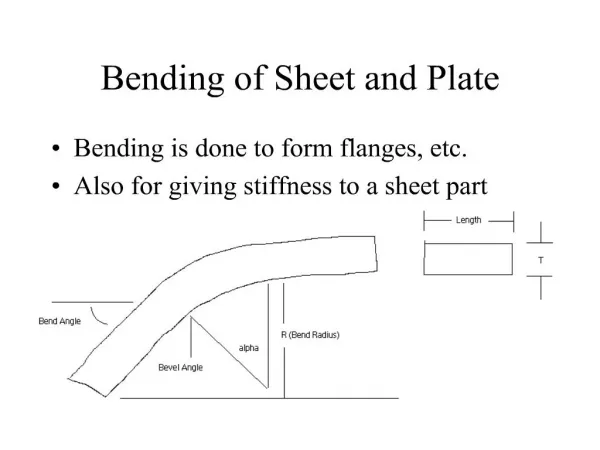
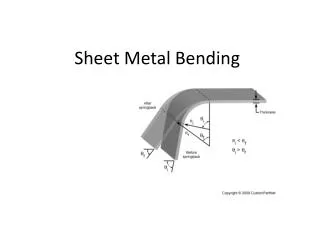
17.1. ElasticPlaneStrainBending 17. Sheet Metal Bending Figure 17.1. Coordinate System for Analysis of Bending Mechanical Engineering Department, GTU
17.1. ElasticPlaneStrainBending 17. Sheet Metal Bending For elastic bending from plane strain asumption elastic strain in y direction is; And when thickness is small the stress in z direction is; Using the above is obtained. Let r be the radius of curvature measured to the mid-plane and z the distance of an element from the mid-plane then elastic strain in x direction is; (17.4) true strain in x direction is; (17.1) (17.2) (17.3) (17.5) Mechanical Engineering Department, GTU
17.1. ElasticPlaneStrainBending 17. Sheet Metal Bending For small strains: But: Placing Eq (17.2) into the above eq.; is obtained. In this case; and E’ is defined as the plane strain elastic modulus. (17.6) (17.7) (17.8) (17.9) (17.10) Mechanical Engineering Department, GTU
17.2. Springback in SheetBending 17. Sheet Metal Bending Here ideal elastic plastic material assumpttion is made. (Yield stregth; Y=constant). For plane strain y= 0. Yield criteria yeids With the sheet metal assumption is obtained. If the above equality is placed in the von Mises equivalent stress equation; is obtained. Thus from yield condition; is obtained. (17.11) (17.12) Mechanical Engineering Department, GTU
17.2. Springback in SheetBending 17. Sheet Metal Bending Figure 17.2. Strain and stress distribution across sheet thickness. Bending strain (a) varies linearlyacross the section. For the non-work hardening stress-strain relation (b), the bending momentcauses the stress distribution in (c). Elastic unloading after removal of the loads results in theresidual stresses shown in (d). Mechanical Engineering Department, GTU
17.2. Springback in SheetBending 17. Sheet Metal Bending In the Figure 17.2 (c) in order to form stress distribution we need to calculate bending moment; M. Thus: For ideal plastic material with the assumption of neglectable central elastic deformation; Here is defined to simplfy the formulation. According to this; (17.15) term is obtained. (17.13) (17.14) Mechanical Engineering Department, GTU
17.2. Springback in SheetBending 17. Sheet Metal Bending Example 1: A steel sheet, 0.036 inches thick, is bent to a radius of curvature of 5.0 inches. The flow stress; Y=33*103 psi (i.e. o=33*103 psi ).E’= 33*106 psi. • What fraction of the cross section remains elastic? • What percent error does neglecting the elastic core cause in the calculation of the bending moment? Solution : 1. The elastic strain at yielding is ex=0/E, where E’ is the plane-strain modulus, E/(1-n2). The limit of the elastic core will be at z = r ex = r 0 / E’ . E’= 33*106 psi, z= 5*33*103 /33*106= 0,005 inch. The elastic fraction is 2*0.005/0.036 =0.28 or 28 %. Mechanical Engineering Department, GTU
17.2. Springback in SheetBending 17. Sheet Metal Bending 2. To calculate the bending moment, for the elastic portion (0 ≤ z ≤ 0.005) x = εxE’=zE’/r and for the plastic portion( 0.005 ≤ z ≤ 0.018 ) , sx = s0 and bending moment; Using the equation which neglects the elastic core, Here, The error is ( 10.69 – 10,.42 ) / 10.42 = 0.026 or 2.6 %. Mechanical Engineering Department, GTU
17.2. Springback in SheetBending 17. Sheet Metal Bending The external moment applied by the tools and the internal moment resisting bending must be equal, so Eq. (17.15) applies to both. When the external moment is released, the internal moment must also vanish. As the material unbends (springs back) elastically, the internal stress distribution results in a zero bending moment. Since the unloading is elastic, M+∆M=0 (17.16) Since the unloading is elastic, ∆x=E’ ∆ex (17.17) The change in strain is given by where r’ is the radius of curvature after springback. This causes a change in bending moment, DM of (17.18) (17.19) (17.20) Mechanical Engineering Department, GTU
17.2. Springback in SheetBending 17. Sheet Metal Bending Since after springback, if Eq (17.15) and Eq (17.20) are equated: or: The resulting residual stress, This is plotted in Figure (17.2.d). Note that on the outside surface where z=t/2 the residual stress is compressive, ’x = -o/2 dir. and on the inside surface z=-t/2 it is tensile ’x = +o/2. (17.21) (17.22) (17.23) (17.24) Mechanical Engineering Department, GTU
17.2. Springback in SheetBending 17. Sheet Metal Bending A similar development can be made for a work-hardening material. If then, where dir. Finally, Since ∆M is still described as before and after spring back, Finally, (17.25) (17.26) (17.27) Mechanical Engineering Department, GTU
17.2. Springback in SheetBending 17. Sheet Metal Bending The variations of x, ∆x, and ’x through the section are shown in Figure 17.3. The magnitude of the spring back predicted can be very large. Figure 17.3. Stress distribution under bending moment and after unloading for a work-hardening material. Mechanical Engineering Department, GTU
17.2. Springback in SheetBending 17. Sheet Metal Bending Example 2: Find the tool radius necessary to produce a final bend radius of r’=10 in. in a part made from a steel of thickness 0.03 inches. Assume a yield stress of 45.000 psi (0=45.000 psi) . Solution : , t=0.03, psi, Using above equation: r=4.2 in. Note: The springback problem is actually greater, since at a bend radius of 4.2 inches, the elastic core is z=r0/E’=4.2x45x103/33x106=0.0057 in. i.e., 38% of the cross section. This introduces 5 error in the moment value. Mechanical Engineering Department, GTU
17.3. BendingwithSuperimposedTension 17. Sheet Metal Bending Such allowances for spring back would cause severe problems in tool design, but fortunately there is a relatively simple solution. Often, as in stretch forming, the tooling does not apply a pure bending moment as assumed above. Rather, tension is applied simultaneously with bending. With increasing tensile forces,Fx , the neutral plane shifts towards the inside of the bend and in most operations, this tension is sufficient to move the neutral plane completely out of the sheet so thatthe entire cross section yields in tension. For such a case, the strain and stress distributions are sketched in Figure Figure 17.4. Figure 17.4. Bending with superimposed tension. With sufficient tension, the neutral axis moves outof the sheet so the strain is tensile across the entire section, (a). With the stress-strain curve shownin (b), the stress distribution in (c) results. After removal of the moment, elastic unloading leavesvery minor residual stresses, as shown in (d). Mechanical Engineering Department, GTU
17.4. SheetBendability 17. Sheet Metal Bending If bend radius is too sharp, excessive tensile strain on outside surface can cause cracking, whilebuckling can occur on the inside surface.Thelimitingvalues ofr/t have been shown to be function of the tensile ductility (% of elongation at fractureor % of area reduction at fracture). where R = inside radius of curvature (i.e. R/t=r/t-1/2), And ( ). (17.28) Mechanical Engineering Department, GTU
17.4. SheetBendability 17. Sheet Metal Bending The above correlation is not accurate for sharp bends (low r/t), because the neutral axis shifts from the mid-plane and the amount of shift depends upon the applied tension and the frictional conditions. With tight bends (small r/h) the neutral axis shifts toward the inside; there are several reasons for this. Mechanical Engineering Department, GTU
17.4. SheetBendability 17. Sheet Metal Bending Figure 17.5. Correlation of limiting bend severity, R/t, with tensile ductility Mechanical Engineering Department, GTU
17.4. SheetBendability 17. Sheet Metal Bending The cross section at the inside will increase while the outside decreases and the magnitude of the true strain (and hence the flow stress in a work-hardening material) increases faster with z in compression than tension. As a consequence, the neutral axis moves inward to compensate for the higher stresses and greater cross section. In non-symmetric sections, transition from elastic to plastic flow will not occur simultaneously on both sides of the bend and, consequently, as yielding starts, there will be a shift of the neutral axis toward the heavier sections. Mechanical Engineering Department, GTU