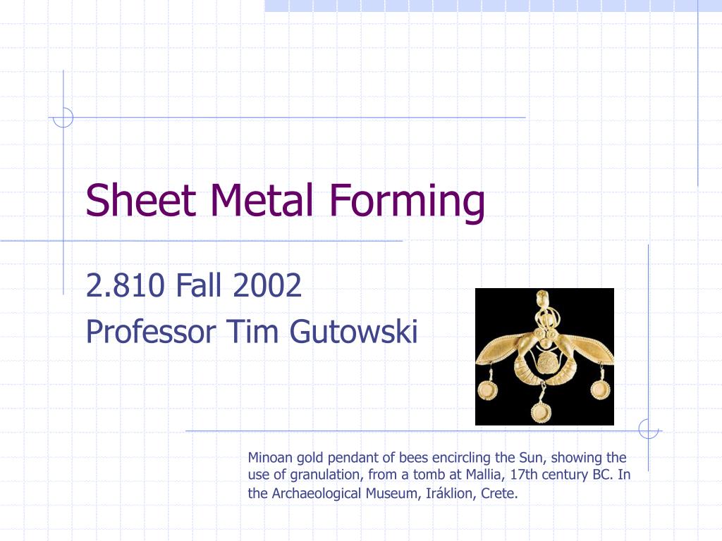
Sheet Metal Forming. 2.810 Fall 2002 Professor Tim Gutowski. Minoan gold pendant of bees encircling the Sun, showing the use of granulation, from a tomb at Mallia, 17th century BC. In the Archaeological Museum, Iráklion, Crete. Historical Note;.
Une image / un lien ci-dessous est fourni (tel quel) pour télécharger la présentation
Politique de téléchargement : le contenu du site vous est fourni TEL QUEL pour votre information et votre usage personnel ; il ne peut être vendu, concédé sous licence ni partagé sur d’autres sites sans l’accord de son auteur.Le contenu vous est fourni TEL QUEL, pour votre information et votre usage personnel uniquement.Téléchargez la présentation en cliquant sur ce lien.Lors du téléchargement, si vous ne parvenez pas à télécharger une présentation, l’éditeur a peut-être supprimé le fichier de son serveur.Pendant le téléchargement, si vous ne parvenez pas à obtenir une présentation, le fichier a peut-être été supprimé par l’éditeur.
F I N
Plus de contenu associé
Transcription de la présentation
Sheet Metal Forming 2.810 Fall 2002 Professor Tim Gutowski Minoan gold pendant of bees encircling the Sun, showing the use of granulation, from a tomb at Mallia, 17th century BC. In the Archaeological Museum, Iráklion, Crete.
Historical Note; Sheet metal stamping was developed as a mass production technology for the production of bicycles around the 1890’s. This technology played an important role in making the system of interchangeable parts economical (perhaps for the first time).
Sheet T Punch D Die Part or slug Shearing Operation Force Requirement F = 0.7 T L (UTS) T = Sheet Thickness L = Total length Sheared UTS = Ultimate Tensile Strength of material
t Y/2 s Y Yield Criteria tmax = (1/2) Y tmax = (2/3)1/2 Y Tresca Mises
Workpiece Die Bending Force Requirement Force Punch T = Sheet Thickness W = Total Width Sheared (into the page) L =Span length UTS = Ultimate Tensile Strength of material T L Engineering Strain during Bending: e = 1/((2R/T) + 1) R = Bend radius Minimum Bend radius: R = T ((50/r) – 1) r = tensile area reduction in percent
Stretch Forming Force Requirement F = (YS + UTS)/2 * A F = stretch forming force (lbs) YS = material yield strength (psi) UTS = ultimate tensile strength of the material (psi) A = Cross-sectional area of the workpiece (in2) • Example of Force Calculation • Calculate the force required to stretch form a wing span having a cross-sectional area of .50X120” made from 2219 aluminum alloy having a yield strength of 36,000 psi and a UTS of 52,000 psi: • F = 88000/2 * 60 = 2,640,000 lbs = 1320 tons • Calculate the force required to shear a 10” diameter, 1/8” thick blank from mild steel with a UTS of 45,000 psi: • F = 0.7 (.125)(p)(10) 45,000 = 62 tons
Auto body panels • 10 - 11 panels • 3 to 5 dies each • ~$0.5M each • ~$20M investment
Material Selection Material selection is critical in both product and process design. Formability is the central material property. This property must be balanced with other product and process considerations such as strength, weight, cost, and corrosion resistance. Auto vs. Aerospace Example Auto Body Panel Airplane Body Panel Progressive stamping stretch forming 1010 Steel, cold-rolled 2024 Aluminum, T3 temper .04” sheet, custom order .08” sheet, oversize Double-sided Zinc clad mechanically polished Cost ~ $.35-.45/lb Cost ~ $4.0/lb UTS ~ 300 MPa UTS ~ 470 MPa YS ~ 185 MPa YS ~ 325 MPa Elongation ~ 42% Elongation ~ 20% n = .26 n = .16
Aerospace Stretch Forming Body Panel Process Parts Received Mylar Protection Applied ‘Burr’ Edges in tension Stretch Forming Index to Block Clad and Prime Surfaces Chemical Milling ‘Burr’ Edges and Inspect Hand Trim Process Flow for Automobile Door Stamping Operation Raw material Blank material starting dimensions Drawing Pierce Restrike Flange
Design: Stretch Forming vs. Stamping • Stretch Forming Advantages over Stamping • Tighter tolerances are possible: as tight as .0005 inches on large aircraft parts • Little problem with either wrinkling or spring back • Large, gently contoured parts from thin sheets • Stretch forming Disadvantages over Stamping • Complex or sharply cornered shapes are difficult or impossible to form • Material removal – blanking, punching, or trimming – requires secondary operations • Requires special preparation of the free edges prior to forming
y x h L b r = 1/K M M y sY s E e ey Elastic Springback Analysis • Assume plane sections remain plane: • ey = - y/r (1) • Assume elastic-plastic behavior for material • = E e e e • Y e e
M Loading MY EI EI Unloading 1/r 1/rY 1/R1 1/R0 3. We want to construct the following Bending Moment “M” vs. curvature “1/r” curve Springback is measured as 1/R0 – 1/R1 (2) Permanent set is 1/R1
Y s dA ds b 5. M = As y dA y dy h Elastic region (3) At the onset of plastic behavior s = - y/r E = - h/2r E = -Y (4) This occurs at 1/r = 2Y / hE = 1/rY (5) Substitution into eqn (3) gives us the moment at on-set of yield, MY MY = - EI/rY = EI 2Y / hE = 2IY/h (6) After this point, the M vs 1/r curve starts to “bend over.” Note from M=0 to M=MY the curve is linear.
Y In the elastic – plastic region yY s (7) Note at yY=h/2, you get on-set at yield, M = MY And at yY=0, you get fully plastic moment, M = 3/2 MY
To write this in terms of M vs 1/rrather than M vs yY, note that the yield curvature (1/r)Ycan be written as (see eqn (1)) (8) Where eY is the strain at yield. Also since the strain at yY is -eY, we can write (9) Combining (8) and (9) gives (10)
Eqn(11) M Loading MY EI EI Unloading 1/r 1/rY 1/R1 1/R0 Substitution into (7) gives the result we seek: (11) (12) Elastic unloading curve
Cylindrical Part Error Reduction 6 0 1 . 6 1 . 4 5 0 M A X 1 . 2 R M S 4 0 1 MAXIMAL SHAPE ERROR [x0.001 in.] RMS Error [x0.001 in.] 3 0 0 . 8 0 . 6 2 0 0 . 4 1 0 0 . 2 S Y S T E M E R R O R T H R E S H O L D 0 0 P 1 P 2 P 3 P 4 P A R T C Y C L E