Download

1 / 39
390 likes | 511 Vues
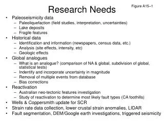
This research outlines the current challenges and future directions in cold bending for structural steel. Key motivations include reducing scrap, improving fit-up efficiency, and standardizing procedures to minimize costly trial-and-error methods. The investigation employs finite element modeling to assess strains and stresses during bending processes, addressing issues such as cracking and dimple formation in flanges. Future work aims to establish guidelines for standardized cold curving, while current assessments focus on the effects of cold bending on fracture characteristics.

E N D
COLD BENDING RESEARCH NEEDS Courtesy S. Kozel UNIVERSITY OF BALAMAND RESEARCH COUNCILJUNE 23rd, 2004
OUTLINE • MOTIVATION • PROPOSED METHOD • PREVIOUS WORK • CURRENT WORK • FUTURE WORK
Cut Curving Flange Flange Flange Scrap
Fit-Up Pressure Applied During Fit-up Web Pressure Applied During Fit-up Flange Flange Fitting Jig
Problems ? • - Costly because of excessive waste • - Too much scrap for sharp curvatures • - Used for mild curvatures (R 300m) • - Fit-up operation too complicated
Heat Curving HEATED AREA
Problems ? • - Trial and error process relying on uneven expansion/contraction. • - Takes time to heat and much longer to cool down. • - Results not known till AFTER cooling. • - If it is not right, process must be repeated. • - Ties up shop, slow and costly.
3-ROLLERS BENDING PINCHING ROLLER Courtesy AISC
Bridges: Current Status ? • Not allowed by AASHTO, concerns: • - Cracking, Fracture • - Flange Upsets • - Dimples • - Web Crippling • No criteria is available • Depends on skill and knowledge of fabricators
TAMPA STEEL TAMPA STEEL 1: Hydraulic jack (bot. flange) 2: Hydraulic jack (top flange) 3: Longitudinal arms 4: Steel plate 5: Clamps
PROPOSED CONCEPT L 2 4 5 3 6 1 7 3 5 max = 4 2 6 x
FULL-SCALE DEMO FULL-SALE DEMO
Top Flange Bending S
Bot Flange Bending 5 7 1: Jack 2: Head 3: Plate 4: Angle 5: Support 6: String Line 7: Stiffener 1 4 2 3 6
FORMULATION • PARAMETERS: • - Load Frame Spacing S • - Bending Loads Ptf, Pbf • - Deflection within span S • - Segment Length Li • - Number of Segments n • - Offsets S Li Ptf
Comp. side Flange S = Lp LOAD FRAME SPACING (S) • Based on lateral bracing limit: • S = 14.4c for Grade 250 steel • S = 12.2c for Grade 345 steel • For unsymmetrical sections use ctf Load P Flange Width 2c
BENDING LOADS (Ptf, Pbf) • From simple beam plastic load analysis: Top Flange: Ptf based on ttf, ctf Bot. Flange: Pbf based on tbf, cbf Constant P Fytfc c Fytfc c Mp = Fytfc2 S
DEFLECTION ctf cbf Ptf Pbf Load P tf bf set = cte = tf bf ??? bf Plastic Hinge tf Set P = Pbf, Load in cycles m=tf/bf P Pbf (not in this scope) S
SEGMENT LENGTH Li 2Li tf S [m] Constant [m-1] [m+1] 2Li 2Li/S Radius R
Length L nLi a a n n+1 2 4 5 3 1 Line of symmetry NUMBER OF SEGMENTS n Round-down to the nearest even integer adjust
OFFSETS ii, ij 2 6 7 1 3 5 4 Load: 2 22 Load: 3 23 33 Load: 4 24 34 44 Load: 5 25 35 45 55 Load: 6 max 26 46 36 56 66
FABRICATION AIDS (LOADS) Ptf =0.462.5152 = 260kN,Pbf =0.465252 = 1440kN P/tfc2(kN/cm3) G 400 G 345 0.46kN/cm3 G 250 S (cm) 215cm
FABRICATION AIDS (Deformations) tf = 3.5/15 = 0.23cm,bf = 3.5/25 = 0.14cm G 400 G 345 round-up to 2 G 250 c (cm2) 3.5cm2 S (cm) S = 215cm S (m)
FABRICATION AIDS (Multiple Load) G 400 Bot. Flange load /(S2/c)105 G 345 G 250 = (tf – bf)=0.09cm [/(S2/c)]105 = 4.9. 4.9 Px/tfc2/S (kN/cm2) S (m) R/c (cm/cm) 97 Px=975(25)2/215=1400kN (kN/cm2)
FABRICATION AIDS (Segments) G 400 G 345 Li=0.25215=53.75cm n=(1200–215)/53.75= 18.3 Round-down to n=18. Li=(1200–215)/18= 55 cm G 250 Li/S cm/cm) 800 S (m) R/c (cm/cm)
SUMMARY • - Development of a standardized cold curving procedure. • Relationships (loads vs. deformations), Fabrication Aids are now available. • - Limits are set on maximum strains (plastic) • Note: Residual stresses may be released by heat treatment
Sen,R., Gergess,A. & Issa,C. “Finite Element Modeling of Heat-Curved I-Girders” ASCE Journal of Bridge Eng, Vol. 8, No. 3, May/June 2003,pp.153-161. • Gergess A. & Sen R. (2003). “Simplified Heat-Curving Analysis”. Journal of Transportation Research Board, No. 1861, Construction, pp. 101 - 114 • Gergess, A. & Sen, R. “Inelastic Response of Simply Supported I-Girders Subjected to Weak Axis Bending,” Proceedings of the International Conference on Structural Engineering, Mechanics and Computation, Cape Town, South Africa, Edited by A.Zingoni, Vol. I, pp 243-250, 2001. • Gergess, A. and Sen R. “Fabrication Aids for Cold Straightening Structural Steel Girders”. AISC, EngineeringJournal (in press), 2004. • Gergess, A. and Sen R. “Cold Curving Un-symmetric Un-stiffened Steel Girders, Journal of Constructional Steel Research, London, UK (in press), 2004. PUBLICATIONS
Current Work • Theoretical Investigation: 3D Finite Element Modeling
Current Work Strain Hardening Loading Fy max 10 y STRESS Un-Loading y STRAIN residual 8.5y
Current Work • Effects of Cold Bending on Steel mainly fracture characteristics: • Perform Visual • Inspection using • NDT Techniques
Acknowledgments • Samuel & Julia Flom Fellowship: USF • Dr. Rajan Sen • Ronald Medlock, Texas DOT “Performance and Effect of Hole Punching and Cold Bending on Steel Bridges”. Research project conducted by University of Texas at Austin and Texas A&M University, 2003. • TRB/AASHTO/NSBA