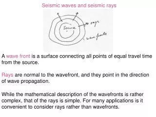
SEISMIC DESIGN STEPS
SEISMIC DESIGN STEPS. Er.T.Rangarajan,B.E,M.Sc(Struct.Engg), Consulting structural engineer. STEPS IN SEISMIC DESIGN:. A.PLANNING STAGE: Plan the building and structures in a symmetrical way both in plan (horizontal axis) and elevation. (vertical axis).

SEISMIC DESIGN STEPS
E N D
Presentation Transcript
SEISMIC DESIGN STEPS Er.T.Rangarajan,B.E,M.Sc(Struct.Engg), Consulting structural engineer.
STEPS IN SEISMIC DESIGN: A.PLANNING STAGE: • Plan the building and structures in a symmetrical way both in plan (horizontal axis) and elevation. (vertical axis). • Avoid open ground (Soft storey) which is used for car parking. • Avoid weak storey and provide strong diaphragm. That is thinner slabs and flat slabs are to be avoided. • Provide openings for doors and windows at a distance of min 0.6 m from the column edges. Follow the IS code 4326 –page 11-for more details for masonry structures. • Do not add appendages like water tanks and swimming pools etc which will create a vast difference of Cm and Cr. (Center of Mass & Center of rigidity)
6. Conduct soil test and investigate the soil nature to avoid soil liquefactions. 7. Follow the IS codal and NBC provisions while in Planning stage which will aid more safer structures. 8. Select good materials-concrete ingredients, brick, steel etc. Specially steel having an elongation of above 14% and yield strength of 415N/mm^2. 9. The yield stress shall not be greater than 415N/mm^2. Steel having an yield strength 500 N/mm^2 may be used provided the % of elongation is above 14%. Make sure before approving it by means of lab. test results. 10. Provide plinth beam at ground level , lintel and roof band (masonry structures). 11. Do not lower the beams in RCC frames at lintel level to have financial savings since the load path will not be there.
GEOMETRY:(ref: page 624 to 628 of earthquake Design concept-by Dr.C.V.R.Murthy) • Building need to be proportioned reasonably to avoid unduly long, tall or wide dimensions which are known to result in poor seismic performance during an earthquake. Thus urban by-laws tend to control the overall geometry of the buildings with respect to the plot size. These are helpful in controlling problems like blockade of roads or collapsing on adjacent buildings in an unfortunate situation of a building collapse during an earthquake. • Height/plot width <1.3 as per clause 6.6 NBC(1983)(part III) for plot size and clause 9.4.1 for height. Ex: plot area 10.0x18.0m-Max.permissible height= 1.3x10=13.0m • Length to width ratio<1.66 Clause 6.6 NBC & 8.2.1 for side open space. • Ex: helps in ensuring rigid diaphragm action.
Plot area 12mx20m -deduct standard setbacks. -Remaining maximum coverage area:6.0mx15.5m. -Maximum possible plan size: 6mx9.6m. LENGTH OF BUILDING: • Shall not be more than 150m. • Clear height of 6m at every 30m intervals at ground level for a passage of 7.5m width. 7.5m 6m 30m 150m (max)
Thermal consideration requires expansion joints after every 45m. These joints become seismic joints in buildings locates in seismic zones. In such situations, the 150m specified is not relevant. • OTHER CONSIDERATIONS: • IS 1893 Provisions. -Improve shape and subsequently behavior of building during earthquake shaking. Design provisions may not exist to explicitly limit the height of buildings. But, it is desirable to ensure that - Buildings are not made too long. - Building height gives a regular (desired) slenderness ratio.
B.DESIGN STAGE:Structural analysis: • The structural designer should address the influence of masonry infill walls in the lateral force behavior of the structure, either by taking them into account in the design process or • By a separation gap from the column. If a separation gap is provided, then appropriate measures should be taken to warrant the out-of-plane stability of the masonry when subjected to lateral forces from wind or earthquake. The gap min 20 mm to50mm or but comply with calculation. • Avoid weak column and strong beam design. • Provide thick slab which will help as a rigid diaphragm. Avoid thin slab and flat • slab construction. • Provide cross walls which will stiffen the structures in a symmetric manner. • Provide shear walls in a symmetrical fashion. It should be in outer boundary to have large lever arm to resist the EQ forces.
FOR CANTILEVERS IT IS DESIGNED FOR GRVITY ANFD OTHER LOADS AS USUAL FOR THE TOP BARS AND THICKNESS BUT DESIGNED IN ADDITION TO THAT AS PER THE IS CODE 1893-2002 CLAUSE 7.12.2.2 which states: All horizontal projections like corniced and balconies shall be designed and checked for stability for five times the design coefficient specified in 6.4.5(that is =10/3 Ah). .{Vb=AhW} For design example wide page 335 of ADVANCED R.C. DESIGN BY P.C. VARGHESE. HOW TO INCREASE THE DUCTILITY : Ductility is defined as the ability of a structure to undergo inelastic deformations beyond the initial yield deformation with NO DECREASE IN THE LOAD RESISTANCE. CAN BE INCREASED IN A SECTION BY: • Decrease the percentage of tension steel (pt). • Increase the percentage compression steel (pc). • Decrease in the tensile strength of steel. (Fy=415N/mm^2). • Increase in the compressive strength of concrete.-Min M20 to M30 and above. • Increase in the compression flange area in flanged beams (T and L beams) and • Increase in the transverse (Shear) reinforcement.
CAPTIVE COLUMNS: Captive column Beam opening opening opening column column masonry masonry masonry • Solution: • Add ties at closer spacing. Preferably spiral ties. • Provide masonry walls on either side equal to twice the opening sizes by reducing the openings. • The best solution is to avoid the opening so that no captive column is created.
CAPTIVE COLUMNS: SOLUTIONS. Beam L L L L L 2 1a OPENING 1 OPENING OPENING column column masonry masonry masonry
SOFT STOREY: This case is usually by providing car park at the ground floor. In this case try to provide masonry walls as possible as to provide stiffness to columns. If not possible design the columns and beams in soft storey for moments and shears by 2.5 times from the analysis results. Clause 7.10.3a –IS 1893(part1)-2002
b)Besides the columns designed and detailed for the calculated storey shears and moments, shear walls placed symmetrically in both directions of the buildings as far as away from the centre of the buildings as feasible; to be designed exclusively for 1.5 times the lateral storey shear forces calculated as before. (clause 7.10.3.b) In another solution is to provide (cross bracings (in elevation) without hindrance to vehicular movements. L,T, + SHAPE COLUMNS CAN BE USED BUT DESING IS A STILL A MATTER .
SOME BASIC BRACING TYPES: DIAGONAL BRACING X- BRACING V- BRACING INVERTED V- BRACING K- BRACING
DETAILING: • GOOD DETAILING IS AS IMPORTANT AS DESIGN AND PLANNING. • FOLLOW THE DUCTILE DETAILING AS PER IS CODE 13920-1993. ANCHORAGE AND OVERLAPPING ARE TO BE AS PER THE CODE. • IS CODE 4326-1993-EARTHQUAKE RESISTANT DESIGN AND CONSTRUCTION OF BUILDNGS-IS TO BE FOLLOWED.
CONSTRUCTION STAGE: • Good planning and design will not alone aid in resisting seismic forces but good workmanship and construction practice will add more strength for resisting the seismic forces. • Select good materials . Follow the mix design as obtained by the lab. • Provide the covers as per codal provisions. Do not use the aggregates, marble pieces and other means except the mortar cover blocks. • Follow the design details as furnished by the structural engineer and do not make any deviations. • Compact the concrete by means of needle vibrator. • Cure the concrete for at least a minimum period. • Experienced supervisor should be employed to have good quality control at site.