Building a Winning Robot: From Game Strategy to Drive Trains
Learn the essential steps to design and build a successful robot for competition. Understand the game, develop a winning strategy, and focus on attributes like drive trains and game-piece manipulator designs. Utilize CAD for virtual prototypes and prototype your design to perfection. Explore different types of wheels like KOP, VersaPro, and Colsons, and choose the best option for your robot. Discover advanced concepts like Meccanum wheels and Swerve drive for enhanced maneuverability. Experiment with modular hybrid drive units for versatility and power. Dive into examples and tips for creating custom drive trains and chassis for your robot.

Building a Winning Robot: From Game Strategy to Drive Trains
E N D
Presentation Transcript
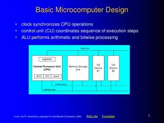
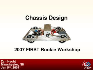
Design / Build Basic Steps: • Understand the Game • Game Strategy – How to win at the game • Robot Attributes required to win a game • “Strategic Design” • Drive train – A good drive train is a must – it allows you to play • Game-piece manipulator designs – difference maker • 3 subsystems • Prototype, and refine (Repeat as necessary) • Use of CAD – virtual prototypes can reduce development time • Get done early – and practice, practice! & Refine some more!
Wheels • KOP – AndyMark Options – 4” @ $6/wheel • KOP HiGrip wheels are good wheels for drive on carpet • AM quotes m = 1.07 • Reasonable on smooth surfaces (reported not tested) • Traction tread wheels • Possibly invented by the Techno-nuts (team 155 Berlin CT) • Conveyor tread improves friction coefficient to ~ 1.1or more • Good also on smooth (test data?) • Conveyor tread is replaceable (riveted on) • Conveyor tread prone to coming off at some point • Variants sold by AM & VexPro • Use blue nitrile conveyor tread (from McMaster) • http://www.mcmaster.com/#standard-conveyor-belts/=olycq0 • Good friction, better wear and its blue!
Wheels • Versapro Versa Wheel • Cheap $5 (vs. $10 one time + $4.33 for tread) • Need to replace entire wheel when tread is worn • Wear rate difference= ?? • Need to use all 6 retaining screws – and Locktite or other? • Good forward traction on rug : mu = 1.3(!?) • When new – wears pretty quick (1 competition) • ‘Cleat’ effect on rug • sideways? or on smooth surface? • May be questionable on polycarbonate surface (2012 bridge)? http://www.vexrobotics.com/vexpro/wheels-and-hubs/217-2903.html
Wheels • Colsons • Hubs available from WCProducts & RobotMarketplace • Design by Justin Foss – Team 558 Mentor • $8 per wheel, $13 per hub • Good durability to traction • Never need replacement • Good traction on smooth surfaces • Some teams (228) cut grooves for enhanced traction • Very popular by some top teams • Locally – 558, 228, 2168 all use them (also many top world teams)
Wheel Trade Matrix • This is a somewhat subjective ranking • Let’s get some data and make it objective? • Focus on best options – Roughtop, Versapro, HiGrip KOP, and Colsons friction test • Different games will weight different attributes differently
Wheels Meccanum Allows easy implementation of “Holonomic” drive • Ability to strafe and rotate independently, fun As seen in recent Star Trek Movies! (forklift scenes) https://www.youtube.com/watch?v=vAiwLRGsNrE Used in 2011 “Logomotion” by Apple Pi Allowed easy alignment of tubes to pegs and for minibot deployment http://www.applepirobotics.org/media/videos-2/ • Look at ~2:40 & 11:20 Shortcoming is pushing power Angled wheels lose 30% of their pushing power In 2011 in CT finals we were shut down due to pushing power Top national teams have said they put Meccanums on DNP list. https://www.youtube.com/watch?v=8XkgUBZqWdA Another view of a basic meccanum
Modular Hybrid drive units Units can be rotated and then act as tank drive (Octanum) • Hybrid drive actuated typically by pneumatics • Provides maneuverability of Meccanum • With pushing power when needed • Extensive driver training required
Swerve Drive = Crab + Rotation Unicorn – fully independent drive allows Strafe + Rotation No skidding when turning and immediate change in direction improves speed and strength “Superposition” – Vector Addition + = “Unicorn” or Fully Independent Swerve Each wheel to be driven and steered independently, Also able to turn infinite rotations 8 motors required, requires 4 PID Feedback controls Strafe Rotate • Demo the “Swerve Tester 8” spreadsheet • Make Labview program that reads XYZ Joystick input and sets angle and speed indicators
Swerve Examples 1717: https://www.youtube.com/watch?v=rVDy4-b_hxo Ability to instantly change direction translates to speed Apple Pi Prototype: http://www.applepirobotics.org/media/videos-2/ • Test it with bumper and weight vs. 2013 tank drive • at SpookTacular!
Drive Motors (and Transmissions) • For many years CIM motors have been the staple of drive trains • 2, 4, 6 CIM drives (4 most common, 6 was great for 2013, 2 all needed in 2009) • Generally want all the CIMs you can have on your drive train • 3 CIM allows for full torque single speed (no need for 2 speed?) • Supershifters (AM) 2 speed gearboxes used 2 of last 4 years, takes lots of driver training – unless automated…..! • Test opportunity on 2012 robot.
Drivetrains / Chassis • Team 610 (world champs) simple/ custom • 6 CIM Drive custom gear train • All CIMS low to maximize low c.g – note battery clamp low and in the middle also. • Frame is all bolted together with spacers. • Threaded rod through 1 in square channels. • Precision machining for custom gear drive • Otherwise simple machining • VersaPro Wheels • Dead Axle set up
Miss Daisy’s 8 wheel drive – 2012 (Einstein)80/20 material frame, 6” wheels packed tight for bump Note also simple COTs components and layout – clean, not difficult Blue Nitrile Tread from McMaster Bearing blocks (allow easy chain or belt tightening ) Live Axle Set-up
West Coast Drive 6WD or 8WD • Team 254 – Cheesy Poofs • Maximizes width of wheel base • Wheels are over hung • Axles have 2 bearings in a 1x2 box section • Typically a cam chain/belt tensioning system • More space inside • Light weight – uses bumpers as part of structure • Some integrate custom transmission with it • Usually requires higher precision machining You don’t choose a WCD if you have not already developed a base design before the season Some advantages but not necessarily optimum
Sheet Metal Chassis & All gear drive Requires close relationship with Sheet Metal shop Water-jet Bending High precision Strong CAD Team 488
Bearing Blocks How to Conveniently Keep Belts/Chains Tensioned How to conveniently be able to adjust tension and spacing of drive (or other) axles? Or could be: Using Ball bearing – AM or VexPro Different shaft diameters and also Hex • Hex bearings can be hard to get and/or unreliable • Bearing is .25” thick + .0625” flange Design a bearing block to hold bearing and fit 1020 T-slot hardware 80/20)? • Desire bolt hole center distances to be 1” • for use with 1020 t-slot From Robot Marketplace ½” round shaft, cast Iron 1.125” hole with 1.25” counter-bore 1” 5/16” 2012 1020 aluminum
New KOP Chassis – 2D “CAD” Layout and Drive Train for the 2014 AM KOP chassis Wide or Long option – convertible – also assuming 112” perimeter rule stays 2 choices of aspect ratio? (likely – due to different belt lengths required) Tough-box mini 10.7:1 gear ratio = ~ 10.5 fps – 2 CIMs/in gearbox – 6” wheels 6 inch wheels: 4 wheel wheelbase = L = (full robot length – 7” )/2 Wheelbase width = robot width minus 4” - wheel ctr to wheel ctr 31 x 25 robot => 4w wheelbase: 12” , width: 21 , W/L = 1.75 - Not too agile 25 x 31 robot => 4w wheelbase: 9”, width = 27”, W/L = 3.0 - Hard to keep straight Frame height above ground is ~ 2”– implies smooth surface for game? L • Top View • ½ Robot • 6WD, belt drive • Wide or long • Assume 2 sets of belt lengths(?) for 2 out of the box set-ups W/2
Upgrades on New KOP Chassis – 2D “CAD” What can we improve on? Some Possibilities: Optimize our own width to length Change to 4” wheels, Swap out toughbox mini for: Vexpro 3 CIM 6:1 ratio gearbox 12.5 fps, + full torque Or 2 CIM with shifter gearbox (~14 & 5 fps) 8WD or 6WD layouts possible Overall wheel base length is overall length – 5” (10% better than KOP) Drop Frame to 1” height above carpet (lower c.g.) 6WD 8WD Top View ½ Robot
Ronaldo (2010 Robot) Drive Train2D “CAD” example Uses Excel – make grid squares to 20 pixels x 20 pixels Use simple drawing functions to make simple 2D sketches Easily email and communicate design ideas outside of meetings during build Once 2D concept is worked out – can develop 3D Solidworks model 8 wheel drive system – front and back off of ground typically for ease of turning Suspension mounted with springs – to absorb bumps better. 2 speed gearboxes
Ronaldo (2010 Robot) Roller/Kicker Front wheels not displayed in this section view
Littlefoot: Early 2D rendering of CIMple gearboxes with chain drive system 4 independent motor/transmissions required for Meccanum drive. Tank drive only requires 2 - allows for practical use of 2 speed transmissions.
Side view: Top view: Motors would be symmetrical (incorrect in model) Front view: Mecanum wheels being represented by cylinders with same envelope dimension Direct Drive with Toughboxes Would be modified with long shafts and straddle mount bearing – not modeled.
Based on work this afternoon - Elevator slide CAD shown in 4 positionsMaintaining 12” overlap on 48” sectionsProbably more height than needed – but may even allow tube to be held horizontally over top pegs.The weight of what is modeled is about 25#.Note the base shown on the right is the width of the robot…. 122 inches 86 inches 50 inches 8 inches 27”
Based on work this afternoon - Elevator slide CAD shown in 4 positionsMaintaining 12” overlap on 48” sectionsMaybe more height than needed – but may even allow tube to be held horizontally over top pegs.The weight of what is modeled is about 25#. Arm/claw not includedNote the base shown on the right is the width of the robot…. 122 inches 86 inches 50 inches 8*48 + 24 = 408” = 34’ 8 inches 27”
6 views with the robot baseAxial position of lift on robot is just approximate.We better not drive with the lift up!
This layout – does not work! Tube not placed on lowest – 30” peg Can you fix it? Figure out where is arm pivot – height and distance from frame/bumper How many extensions , how long is each? Bonus : Design system with fixed height - no elevator - with telescoping or fixed arm That can reach all pegs a) What is fixed height of pivot? b) What is arm config? does it telescope? claw type?
CAD can make Robot Designs that are cleaner, faster to build