Shafts, Belts, Chains, & Clutches
750 likes | 1.2k Vues
Shafts, Belts, Chains, & Clutches. Shafts – Definition. Generally shafts are members which rotate in order to transmit power or motion. They are usually circular in cross section, and that’s the type we will analyze.

Shafts, Belts, Chains, & Clutches
E N D
Presentation Transcript
Shafts – Definition • Generally shafts are members which rotate in order to transmit power or motion. They are usually circular in cross section, and that’s the type we will analyze. • Shafts do not always rotate themselves, as in the case of an axle – but axles support rotating members. ME 351
Three Common Shafts $ $$ $$$ ME 351
Elements Attached to a Shaft Shoulders provide axial positioning location, & allow for larger center shaft diameter – where bending stress is highest. ME 351
Common Shaft Materials • Typically shafts are machined or cold-drawn from plain hot-rolled carbon steel. Applications requiring greater strength often specify alloy steels (e.g., 4140). • Some corrosion applications call for brass, stainless, Ti, or others. • Aluminum is not commonly used (low modulus, low surface hardness). ME 351
Shafts for Steady Torsion Often the rotating mass & static load on a shaft are neglected, and the shaft is sized simply to accommodate the transmitted power. In such cases, the engineer typically seeks to limit the maximum shear stress max to some value under the yield stress in shear (Sys), or to limit the twist angle . ME 351
Shafts in Steady Torsion Chapter 1 review equations: kW = FV/1000 = Tn/9600 (1.15) hp = FV/745.7 = Tn/7121 (1.16) kW = kilowatts of power F = tangential force (N) V = tangential velocity (m/s) T = torque (N x m) n = shaft speed (rpm) ME 351
SBS Power Units Chapter 1 review equation: hp = FV/33,000 = Tn/63,000 (1.17) where, hp = horsepower F = tangential force (lb.) V = tangential velocity (ft/min) T = torque (lb - in.) n = shaft speed (rpm) ME 351
Steady State Shaft Design Because shafts are in torsion, the shear stress is generally the limiting factor. Recall that max = Tc/J where c = radius, and, for a circular shaft, J = d4/32 As always, use a safety factor of n to arrive at all = max /n ME 351
Limiting the Twist Angle In some cases it is desired to limit the twist angle to a certain value. Recall from Chapter 4: = TL/GJ (4.9) L = length G = shear modulus is always in radians (deg. x /180) ME 351
Example 9.1 Design a solid shaft to transmit 500 kW at n = 1200 rpm. Sys = 300 MPa, and G = 80 GPa. Choose n = 1.5, and limit to < 4o along the 2m length of the shaft. Remember, n = rpm, while n = safety factor. must be in radians in eq. 4.9. ME 351
Combined Static Loads In the preceding example, we considered only the torsional load. Often the shaft loading is more complicated, and both bending and axial loads must be considered as well. Review from Chapter 3: ME 351
Combined Static Load The axial stress is given by: x = Mc/I + P/A = 32M/ D3 + 4P/ D2 (M = bending moment, P = axial load) The torsional stress is given by: xy = Tc/J = 16T/ D3 (T = Torque, J = polar moment of inertia, c = radius) (For circular cross sections.) ME 351
Maximum Shear Stress Theory Typically the axial load P is small compared to the bending moment M and the torque T, and so it is neglected. (Notice how shear is completely omitted.) Recall the maximum shear stress criterion from the Sept. 26th lecture: Sy/n = (x2 + 4 xy 2)1/2(eq. 7.11) ME 351
Maximum Shear Stress Theory Substitute the previous values for x and xyinto eq. 7.11 to obtain: Sy/n = (32/ D3)[M2 + T2]1/2 This equation, or the related eq. for the maximum energy of distortion theory, is useful for finding either D or n. ME 351
Fluctuating Loads In their support of rotating members, most shafts are subject to fluctuating loads, possibly including a shock component as well. We’ve covered fatigue & impact in previous lectures, and that material is directly applied to the design of shafts. ME 351
Example 9.2 Find required dia. of shaft using MDET & Soderberg fatigue relation. Surface is ground. Su = 810 MPa, and Sy = 605 MPa. Torque varies by +/- 10%. The fatigue stress [] factor Kf = 1.4. Temp = 500 oC, and n = 2. Survival rate = 50%. ME 351
Shock Factors In shaft design, shock loading is typically accounted for by yet more fudge factors, Ksb (bending shock) and Kst (torsional shock). The values of these factors range from 1.0 to 2.0. The shock factors are applied to their respective stress components. ME 351
Critical Speeds of Shafts All structures exhibit one or more natural, or resonant frequencies. When a shaft rotates at speeds equal or close to the natural frequencies, resonance may occur. This is usually to be avoided, although some designs feature resonance. Generally the designer tries to keep the speed at least 25% lower than o. But in some cases, the operating speed is higher. ME 351
The Rayleigh Equation ncr = (1/2)[ (gW)/(W2)]1/2 ME 351
Example 9.4 d = 30mm, D = 50mm, E = 210 Gpa. Find ncr ME 351
Shaft Attachments • Many different methods, each with pros and cons of both function, ease of use, and cost: the designer must balance between these factors. • Some methods are very weak compared to the shaft (e.g., a set screw), others are stronger than the shaft itself. ME 351
ShaftAttachments: Keys ME 351
Shaft Attachments: Pins Straight Tapered Roll ME 351
Shaft Attachments: Tapered Clamps www.ringfeder.com ME 351
Stresses in Keys Distribution of force is quite complicated. The common assumption is that the torque T is carried by a tangential force F acting on radius r: T = Fr ME 351
Stresses in Keys • From T = Fr, both shear and compressive bearing stresses may be calculated from the width and length of the key. • The safety factor ranges from n = 2 (ordinary service) to n = 4.5 (shock). • The stress concentration factor in the keyway ranges from 2 to 4. ME 351
Problem 9.20 A 3/8 x 3/8 x 3” long key holds a 3” long hub onto a 1 ½” dia. shaft. The key and the shaft both have an allowable stress of 10 ksi. What is the factor of safety against shear failure if the transmitted torque is 3.5 kip-in.? ME 351
Splines Splines permit axial motion between matching parts, but transmit torque. Common use is automotive driveshafts – check your R/C car. ME 351
Couplings • In many designs involving shafts, two shafts must be connected co-axially. Couplings are used to make these connections. • Couplings are either rigid or flexible. Rigid couplings require very close alignment of the shafts, generally better than .001” per inch of separation. ME 351
Rigid Couplings – Sleeves The simplest type of coupling is the simple sleeve coupling. But this also has the lowest torque capacity. http://www.grainger.com/Grainger/wwg/start.shtml ME 351
Rigid Couplings - Flanged Great web resource: http://www.powertransmission.com/pages/couplings.htm ME 351
Flexible Couplings • There are many types of flexible couplings as well. Generally something flexible is sandwiched in between, or connected to, rigid flanges attached to each shaft. • Alignment is still important! Reaction forces increase with misalignment, and often bearings are not sized ME 351
Two-piece “Donut” (or toroidal) flexible coupling http://viva.rexnord.com/content/features.html ME 351
Universal Joints • U-joints are considered linkages rather than couplings, but serve the same purpose of transmitting rotation. • Very large angular displacements may be accommodated. • Single joints are not constant-velocity. Almost always, two joints are used. The angles must be equal for uniform velocity. ME 351
Shafts parallel but offset Shafts not parallel but intersecting ME 351
It’s Not Nanotechnology, But You Could Get Rich! • Despite decades of research and 1000s of Ph.D. theses, even “highly engineered” shafts fail all too frequently. Even NASA can’t always get it right. • Often the connections are to blame: keys, splines, couplings, and so on. Often fatigue wear failure is the culprit. • The world may beat a path to your door! ME 351
Belts, Chains, Clutches, and Brakes (or, Friction isYour Friend) ME 351
Purchased vs. Designed Components • We went into shafts in some detail because shafts tend to be custom-designed for each application. • Often the components that the engineer puts onto the shaft, however, are purchased. These components can be analyzed as much as one likes, but it’s usually best to work with the manufacturer’s application data. ME 351
Belts and Chains • Economical alternatives to gears for transmitting rotary motion between shafts. Can be lighter, smaller, and as efficient as gears. • However, usually the life is more limited. • Bicycle “gears” (chain drive) versus automotive gears. ME 351
Timing Belts • Toothed or synchronous belts don’t slip, and therefore transmit torque at a constant ratio: great for applications requiring precise timing, such as driving an automotive camshaft from the crankshaft. • Very efficient. More $ than other types of belts. ME 351
Timing Belts ME 351
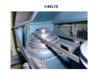
Flat, Round, and V Belts • Flat and round belts work very well. Flat belts must work under higher tension than V belts to transmit the same torque as V belts. Therefore they require more rigid shafts, larger bearings, and so on. • V belts create greater friction by wedging into the groove on the pulley or sheave. This greater friction = great torque capacity. ME 351
V Belt & Sheave Cross Section The included angle 2 ranges between 34o and 40o. ME 351
V Belt Cross Sections (U.S.) ME 351
Flat Belts vs. V Belts • Flat belt drives can have an efficiency close to 98%, about the same as a gear drive. • V belt drive efficiency varies between 70% and 96%, but they can transmit more power for a similar size. (Think of the wedged belt having to come un-wedged.) • In low power applications (most industrial uses), the cheaper installed cost wins vs. their greater efficiency: V belts are very common. ME 351
Flat Belt Drive Example Chapter 13, Problem 1 A flat belt 4 in. wide and in. thick operates on pulleys of diameters 5 in. and 15 in. and transmits 10 hp. Determine: (a) The required belt tensions. (b) The belt length. Given: the speed of the small pulley is 1500 rpm, the pulleys are 5 ft apart, the coefficient of friction is 0.30, and the weight of the belt material is 0.04 lb/in.3. ME 351
Flat Belt Drive Example T = (F1 – F2)r (eq. 13.1) hp = (F1 – F2)V/33,000 = Tn/63,000 (eq. 13.3) sin = (r2 – r1)/c (eq. 13.6) = – 2 (eq. 13.7) Fc = (w/g)V2 (eq. 13.13) F1 = Fc + [ /(-1)](T1/r1) (eq. 13.20) = ef/sin (eq. 13.21) (Where = 90o for a flat belt) ME 351
Flat Belt Drive Example ME 351