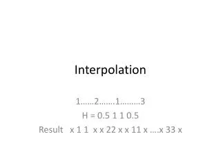
Interpolation
Interpolation. Interpolation. Uniformly spaced zero-crossings in flash ADCs. Ref : R. van de Grift, I. W. J. M. Rutten, and M. van der Veen, "An 8-bit video ADC incorporating folding and interpolation techniques," IEEE Journal of Solid-State

Interpolation
E N D
Presentation Transcript
Interpolation Uniformly spaced zero-crossings in flash ADCs Ref: R. van de Grift, I. W. J. M. Rutten, and M. van der Veen, "An 8-bit video ADC incorporating folding and interpolation techniques," IEEE Journal of Solid-State Circuits, vol. 22, pp. 944-953, issue 6, 1987.
Resistive Interpolation • Intermediate zero-crossings are recovered by interpolation. • DNL is improved by voltage interpolation. • Requires overlapped linear regions b/t adjacent preamps.
Interpolation Nonlinearity (I) • Nonlinear TF of preamps cause errors in the interpolated zero-crossings. • Interpolation nonlinearity directly translates into DNL and INL. • Impedance mismatch due to interpolation also causes dynamic errors.
Interpolation Nonlinearity (II) • Interpolation factor of 4 • Latch input bandwidth • equalized • Critical if input SHA is • not used • Nonlinear interpolation • errors remain Ref: R. J. van de Plassche and P. Baltus, "An 8-bit 100-MHz full-Nyquist analog-to- digital converter," IEEE Journal of Solid-State Circuits, vol. 23, pp. 1334-1344, issue 6, 1988.
Interpolation Nonlinearity (III) • Resistive mesh network • improves impedance • matching at latch input. • 2X interpolation avoids • the interpolation error. Ref: P. Vorenkamp and R. Roovers, "A 12-b, 60-MSample/s cascaded folding and interpolating ADC," IEEE Journal of Solid-State Circuits, vol. 32, pp. 1876-1886, issue 12, 1997.
Capacitive Interpolation K. Kusumoto, JSSC, Dec. 1993
Current Interpolation Less accurate then voltage interpolation due to mismatch of current mirrors Ref: M. Steyaert, R. Roovers, and J. Craninckx, "100 MHz 8 bit CMOS interpolating A/D converter," in Proceedings of IEEE Custom Integrated Circuits Conference, 1993, pp. 28.1.1-28.1.4.
Features of Interpolation • Reduces the total number of preamps by the interpolation factor. • Total number of latches stay the same. • Reduces the total input capacitance (larger input BW). • More area- and power-efficient than straight flash ADC. • Voltage interpolation improves DNL. • Loading of interpolation network decreases the preamp gain/BW. • Subject to preamp nonlinearities.
Inefficiency of Flash ADC Only comparators in the vicinity of Vin are active at a time → low efficiency.
Segmented Quantization Analog pre-processing divides Vin into 2M uniformly-spaced segments. Fine quantization (N-M) bits Segment indicator (M bits)
Signal Folding • Analog pre-processing → folding amplifier • Folding factor (F) is equal to the number of folded segments. Fine quantization N-log2(F) bits Segment indicator (log2(F) bits)
Folding ADC Architecture F = 8 • The fine ADC performs amplitude quantization on the folded signal. • The coarse ADC differentiates which segment Vin resides in.
Folding Amplifier F = 3
Folding Amplifier F = 3 Zero-crossings are still precise!
Zero-Crossing Detection F = 3, P = 4 • Only detect zero-crossings instead of fine amplitude quantization → insensitive to folder nonlinearities. • P parallel folding amplifiers are required.
Offset Parallel Folding F = 3, P = 4 • Total # of zero-crossings = Total # of preamps = P*F • Parallel folding saves the # of comparators, but not the # of preamps → still large Cin.
Signal Folding Pros • Folding reduces the comparator number by the folding factor F, while the number of preamps remains the same. Cons • Multiple differential pairs in the folder increases the output loading. • “Frequency multiplication” at the folder output.
Frequency Multiplication CT vs. DT
Folding + Interpolation Cross-connect P & N sides at the endpoints
“Rounding” Problem F = 3 F = 9 • Large F results in signal “rounding”, causing gain and swing loss. • Max. folding factor is limited by Vov of folder and supply voltage.
Folding vs. Interpolation Folding • Folding works better with non-overlapped active regions between adjacent folders. • Large Vov (for high speed) of folders and low supply voltage limit the max. achievable F. Interpolation • Works better with closely spaced overlapped active region between adjacent folding signals. Observation • Small F and large P (parallel folders) will help both folding and interpolation, but introduces large Cin – approaching flash… • What else can we do?
Cascaded Folding F = 3 F = 9 • Ideal: A large folding factor F can be developed successively. • Small F in the 1st-stage folder → large Vov, less capacitive loading, and less frequency multiplication effect.
Cascaded Folder Architecture (II) F = ? • Simple differential pair-based folding amplifiers • Only works with odd P, compatible with low supply voltage.
Cascaded Folder Architecture (I) F = ? • Gilbert four-quadrant multiplier based folding amplifier • Only works with even P, requires a lot of headroom
Mechanical Model of Cascaded Folding Bult (JSSC’97)
Distributed Preamplification Gain Large signal gain developed gradually along the signal path → from “soft” to “hard” decision
Useful Formulas Assuming a two-stage cascaded folding & interpolating ADC, F1 = 1st-stage folding factor, F2 = 2nd-stage folding factor, P = # of offset parallel folders, I = total interpolation factor, then, Total # of decision level = P*F1*I ADC Resolution = Log2(P*F1*I) Total # of fine comp = P*I/F2 Total # of coarse comp = P*F1 or P+F1? where, usually P = F2 holds.
Circular Thermometer Code F = 4 • Very tight coarse comparator offset requirement (<1/2 LSB) • Aperture delay b/t coarse and fine worsens the problem.
Coarse-Fine Sync (Bit Alignment) • “Coarse” fold indicator with offset thresholds combined with the output of fine comparator A precisely determines which fold Vin resides in. • Large tolerance on coarse comparator offset and aperture delay errors
Useful Formulas Assuming a two-stage cascaded folding & interpolating ADC, F1 = 1st-stage folding factor, F2 = 2nd-stage folding factor, P = # of offset parallel folders (P>F2), I = total interpolation factor, then total # of decision level = P*F1*I, ADC Resolution = Log2(P*F1*I), total # of preamps in 1st folder = P*F1, total # of preamps in 2nd folder = P, total # of fine comparators = P*I/F2, total # of coarse comparators = F1*F2, F1+F2, or F1+P?
Cascaded Offset Bit Alignment (I) • F1 coarse comparators at input and P coarse comparators at 1st-stage folder outputs resolve F1*P (>F1*F2) folds. • One fine comparator output is utilized to perform offset bit alignment.
Cascaded Offset Bit Alignment (II) Two-step offset bit alignment – large offset tolerance on F1 coarse comparators and medium tolerance on P comparators.
References • R. J. van De Plassche et al., JSSC, vol. 14, pp. 938, issue 6, 1979. • R. E. J. van De Grift et al., JSSC, vol. 19, pp. 374-378, issue 3, 1984. • R. E. J. van De Grift et al., JSSC, vol. 22, pp. 944-953, issue 6, 1987. • R. J. van de Plassche et al., JSSC, vol. 23, pp. 1334-1344, issue 6, 1988. • J. van Valburg et al., JSSC, vol. 27, pp. 1662-1666, issue 12, 1992. • B. Nauta et al., JSSC, vol. 30, pp. 1302-1308, issue 12, 1995. • A. G. W. Venes et al., JSSC, vol. 31, pp. 1846-1853, issue 12, 1996. • M. P. Flynn et al., JSSC, vol. 31, pp. 1248-1257, issue 9, 1996. • P. Vorenkamp et al., JSSC, vol. 32, pp. 1876-1886, issue 12, 1997. • K. Bult et al., JSSC, vol. 32, pp. 1887-1895, issue 12, 1997. • M. P. Flynn et al., JSSC, vol. 33, pp. 1932-1938, issue 12, 1998. • M.-J. Choe et al., VLSI, 1999, pp. 81-82. • R. C. Taft et al., JSSC, vol. 39, pp. 2107, issue 12, 2004.