Basic Mechanical Engineering-Hydraulic Turbines
Basic Mechanical Engineering-Hydraulic Turbines. By Mr.B.Ramesh, M.E.,(Ph.D) Research Scholar, CEG, Anna University, Chennai. Associate Professor, Department of Mechanical Engineering, St. Joseph’s College of Engineering, Jeppiaar Trust, Chennai-119. Hydraulic (Water) Turbines.

Basic Mechanical Engineering-Hydraulic Turbines
E N D
Presentation Transcript
Basic Mechanical Engineering-Hydraulic Turbines By Mr.B.Ramesh, M.E.,(Ph.D) Research Scholar, CEG, Anna University, Chennai. Associate Professor, Department of Mechanical Engineering, St. Joseph’s College of Engineering, Jeppiaar Trust, Chennai-119
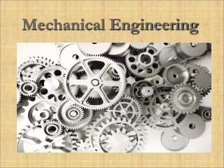
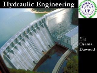
Hydraulic (Water) Turbines Basic working principle: Hydraulic turbines convert the potential energy of water into mechanical work. Three most popular hydraulic turbines are : Pelton wheel (Pelton turbine) Kaplan turbine (Propeller turbine) Francis turbine
Pelton Wheel (Pelton turbine) This turbine is named after Lester A. Pelton (1829 – 1908) an American Engineer who developed it in the year 1880. Pelton wheel is a high head turbine. It is used with heads of more than 500 metres. Note : A head is the distance the water falls before it strikes the turbine blades.
Pelton Wheel (Pelton turbine)… • The flow of water is tangential to the runner. So it is a tangential flow impulse turbine. • A Pelton’s runner consists of a single wheel mounted on a horizontal shaft. • Water falls towards the turbine through a pipe called penstock and flows through a nozzle. • The high speed jet of water hits the buckets (vanes) on the wheel and causes the wheel to rotate. • A spear rod which has a spear shaped end can be moved by a hand wheel. This movement controls the flow of water leaving the nozzle, before it strikes the bucket(vane)
Pelton Wheel (Pelton turbine)… The bucket or vane is so shaped that when the water strikes, it gets split into two and gives it an impulse force in the centre of the bucket. This bucket is also known as splitter.
Kaplan turbine (Propeller turbine) • Kaplan turbine is a type of propeller turbine which was developed during 1900’s by the Austrian engineer Victor Kaplan (1876 – 1934) • Kaplan turbine is a low head turbine and used for heads of less than 80 metres. • The runner of a kaplan turbine resembles with propeller of a ship. That is why, a Kaplan turbine is also called as propeller turbine.
Kaplan turbine (Propeller turbine)… • The turbine wheel, which is completely under water, is turned by the pressure of water against its blades. • Guide vanes regulate the amount of water reaching the wheel.
Francis turbine It is named after James B. Francis (1815 – 1892) an English born inventor who developed the turbine in the year 1849. It is used when the head is between 80 to 500 metres. i.e. it is a medium head turbine. It is a mixed flow reaction turbine.
Francis turbine… • A Francis turbine rotates in a closed casing. • Its wheel has many curved blades called runner vanes as many as 24. • Its shaft is vertical. The wheel of a Francis turbine operates under water. • The guide vanes and stay vanes control the amount of water flowing into the runner vanes. • The runner is rotated mainly due to the weight or pressure of the flowing water.
Hydraulic turbines… Difference between Kaplan turbine and Francis turbine:
Hydraulic turbines… Difference between Impulse and Reaction hydraulic turbines:
Videos and Animations Pelton Francis Kaplan turbine animation