SlideServe
Menu
Préférences
© SlideServe · v2026

Hydraulic Engineering

kalkin avatar
15 diapositives · 634 Views · Aug 25, 2014

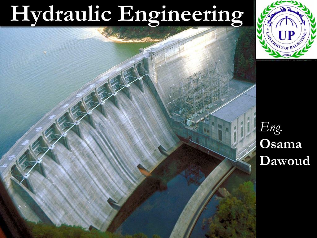
Hydraulic Engineering. Eng. Osama Dawoud. Lecture 6. Branching in Pipelines. Branching pipe systems. Branching in pipes occur when water is brought by pipes to a junction when more than two pipes meet. This system must simultaneously satisfy two basic conditions:
Hydraulic Engineering - slide 1
01 / 15Hydraulic Engineering
1 / 17

Télécharger la présentation

Hydraulic Engineering
Une image / un lien ci-dessous est fourni (tel quel) pour télécharger la présentation

Politique de téléchargement : le contenu du site vous est fourni TEL QUEL pour votre information et votre usage personnel ; il ne peut être vendu, concédé sous licence ni partagé sur d’autres sites sans l’accord de son auteur.Le contenu vous est fourni TEL QUEL, pour votre information et votre usage personnel uniquement. Téléchargez la présentation en cliquant sur ce lien. Lors du téléchargement, si vous ne parvenez pas à télécharger une présentation, l’éditeur a peut-être supprimé le fichier de son serveur.Pendant le téléchargement, si vous ne parvenez pas à obtenir une présentation, le fichier a peut-être été supprimé par l’éditeur.

F I N

Plus de contenu associé

Transcription de la présentation
  1. Hydraulic Engineering Eng. Osama Dawoud

  2. Lecture 6 Branching in Pipelines

  3. Branching pipe systems Branching in pipes occur when water is brought by pipes to a junction when more than two pipes meet. This system must simultaneously satisfy two basic conditions: 1 – the total amount of water brought by pipes to a junction must equal to that carried away from the junction by other pipes. 2 – all pipes that meet at the junction must share the same pressure at the junction. Pressure at point J = P

  4. Consider a case where three reservoirs are connected by a branched-pipe system. There are two types of Branching pipe problem: 1- The problem is to determine the discharge in each pipe and the pressure head at the junction (point J). Four unknowns: Q in each pipe and P at J Given: All pipes parameters All Tanks elevation The solution based on: 1- Assuming the pressure at J and then estimate the value of hf in each pipe 2- Calculate the flow in each pipe and check 3- try the last procedure until

  5. 2- The problem is to determine the flow in two pipes and the pressure head at the Junction J. Three unknown: Q in two pipe and P at J Given: All pipes parameters Q in a pipe two Tanks elevation The solution based on: 1- Determine the pressure at J by calculate hf in pipe with known Q 2- Estimate the value of hf in the other pipe 2- Calculate the flow in the other pipes

  6. Example 1 In the following figure determine the flow in each pipe

  7. Trial 1 ZP= 110m Applying Bernoulli Equation between A , J : V1 = 1.57 m/s , Q1 = 0.111 m3/s Applying Bernoulli Equation between B , J : V2 = 1.08 m/s , Q2 = - 0.212 m3/s

  8. Applying Bernoulli Equation between C , J : V3 = 2.313 m/s , Q2 = - 0.291 m3/s

  9. Trial 2 ZP= 100m Trial 3 ZP= 90m

  10. Draw the relationship between and P

  11. Example 2 In the following figure determine the flow in pipe BJ & pipe CJ. Also, determine the water elevation in tank C

  12. Solution Applying Bernoulli Equation between A , J : Applying Bernoulli Equation between B , J :

  13. Applying Bernoulli Equation between C , J :

  14. Group Work 1 Find the flow in each pipe

  15. Group Work 2 • Determine the flow if • The valve is closed • The valve is open and the flow through the small pipe = 100L/S